Multi-layer surface treatment pad for motorized device

a technology of motorized devices and surface treatment pads, which is applied in the direction of carpet cleaners, instruments, photosensitive materials, etc., can solve the problems of premature delamination of such pads, increased cost, and uncontrollable fluid splashing,

Active Publication Date: 2012-11-06
SC JOHNSON & SON INC
View PDF22 Cites 0 Cited by
  • Summary
  • Abstract
  • Description
  • Claims
  • Application Information

AI Technical Summary

Benefits of technology

[0016]Pads of the present invention use the driving power of a motorized device to apply surface treating formulations, without the need to separately add the formulation at the time of use. The pads are designed to minimize radial spraying caused by the pad being driven when wet, to provide a visual indication of the appropriate attachment point for the driver against the pad, and to provide an attachment point where pressing the driver against the pad also facilitates enhanced release of the chemicals. These pads can be produced at very low cost, and the weld patterns help them avoid premature separation.

Problems solved by technology

However, these motorized approaches typically required separate manual application of a cleaning or other treating formulation to the wall or other surface being treated.
Further, they can sometimes result in uncontrolled splattering of fluid (e.g. if the pad is overwetted).
Moreover, special care had to be taken, at increased cost, to keep such pads from delaminating prematurely.
However, this still left some of the other concerns noted above.

Method used


Image

  • Multi-layer surface treatment pad for motorized device
  • Multi-layer surface treatment pad for motorized device
  • Multi-layer surface treatment pad for motorized device

Examples


Embodiment Construction

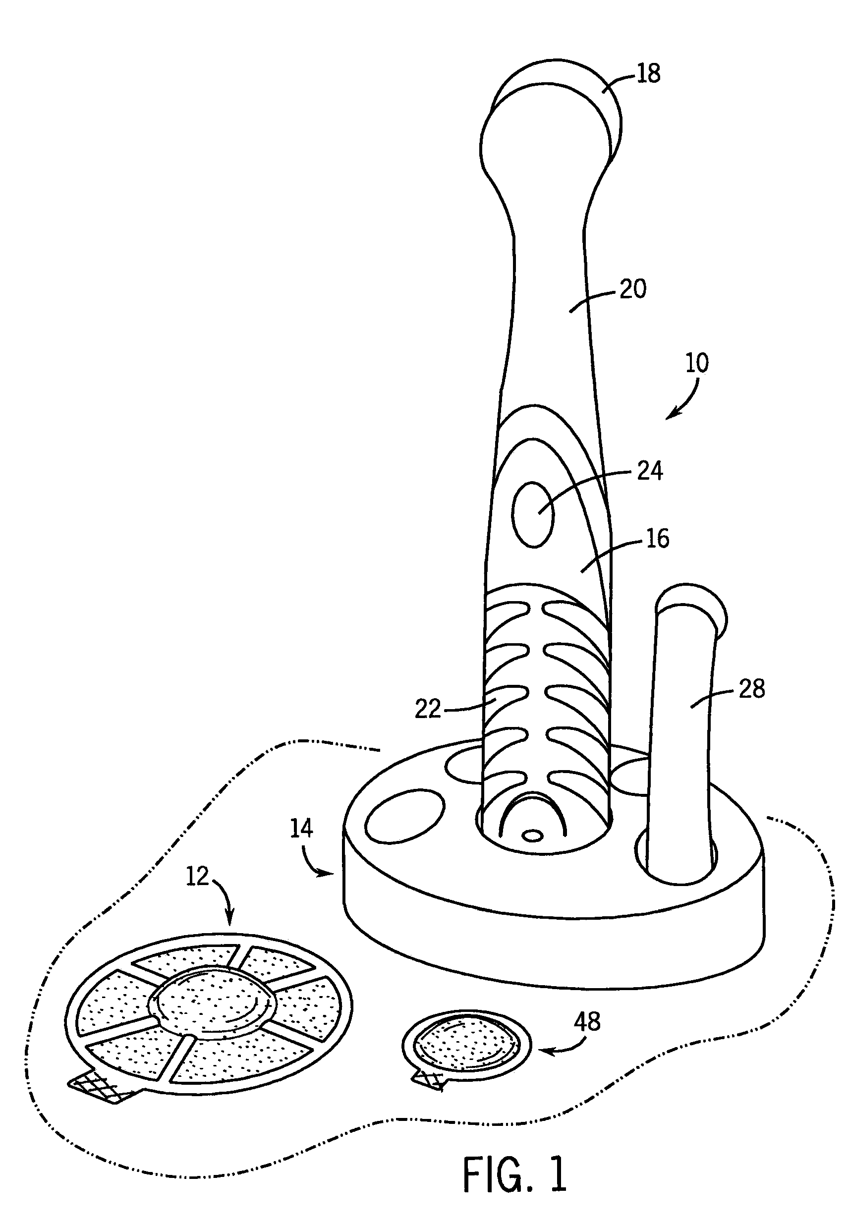
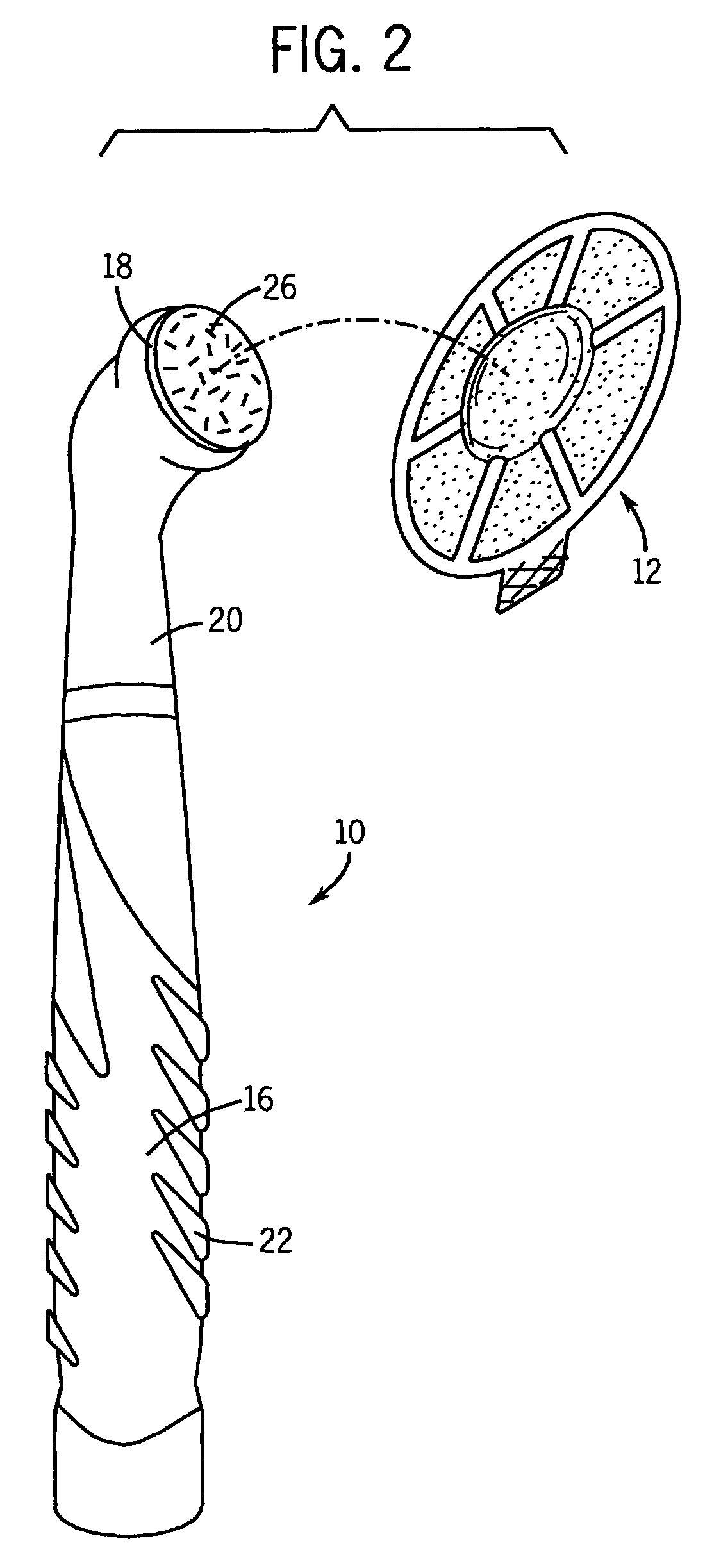
[0025]Referring first to FIGS. 1 and 2, a motorized device 10 is shown adjacent a first cleaning pad 12. The motorized device 10 may be held in a storage tray 14 when the motorized device 10 is not in use. The motorized device 10 is shown removed from the storage tray 14 in FIG. 2.

[0026]The motorized device 10 has a handle 16 and a head 18 at the end of a first neck 20. The handle 16 includes a gripping portion 22 with an overmolded patterned rubber surface to improve the grip of a user holding the motorized device 10. Above the handle 16, in the direction of the neck 20, an on / off button 24 is located in a convenient location for manipulation by a thumb of a user holding the gripping portion 22.

[0027]The on / off button 24 may be toggled to start or stop the operation of an internal motor (not shown) in the motorized device 10 which drives the rotary oscillation of the head 18. Although not shown, the handle 16 receives batteries in its base which supply the energy necessary for powe...


PUM


Abstract

A multi-layer surface treating pad is disclosed. It has an upper layer suitable to serve as one part of a hook / loop type fastener system, a bottom layer which comprises an abrasive or polishing material, and a cleaning or other surface treating formulation positioned between the upper and bottom layer in the form of a bump which is positioned mostly in a central region of the pad. The bump of the formulation causes the upper layer to bulge upwardly so as to provide a visual indication as to where one optimally should attach a motorized device thereto.

Description

CROSS-REFERENCE TO RELATED APPLICATIONS[0001]Not applicable.STATEMENT REGARDING FEDERALLY SPONSORED RESEARCH / DEVELOPMENT[0002]Not applicable.BACKGROUND OF THE INVENTION[0003]The present invention relates to surface treating pads for attachment to a motorized driver device.[0004]To clean a dirty surface it is common to use a chemical cleaning formulation with wiping or brushing to loosen and remove debris, dirt, and the like from the surface. Similarly, to work in a polish or wax on furniture or a floor one often rubs it in with a rag or the like.[0005]Motorized force can more easily clean or polish a surface, or otherwise treat it. Some prior art devices have abrasive wheels or polishers that are motor driven. For example, SonicScrubbers markets a replaceable abrasive pad mountable on a rotary oscillating driver to facilitate the pad cleaning hard surfaces (such as those typically found in the home).[0006]However, these motorized approaches typically required separate manual applica...

Claims


Application Information

Patent Timeline
Patent Type & Authority Patents(United States)
IPC IPC(8): A47L11/162A47L11/164
CPCA47L11/1625A47L11/4038A47L11/408A47L13/17A47L13/312
Inventor HARRIS, JENNIFER R.PRZEPASNIAK, ANN MARIEKNOPOW, JEREMY F.
Owner SC JOHNSON & SON INC
Why Eureka
Try Eureka