Hook structure of power tool

a technology of power tools and hook arms, which is applied in the direction of wrenches, traveling carriers, screwdrivers, etc., can solve the problems of reducing the operability of the power tool, the inability to fully retract the hook arm, and the inability to receive and house the hooks in the receiving portion. , to achieve the effect of reducing the amount of protruding sliding members from the power tool, improving operability in altering the position of the hook arm

Inactive Publication Date: 2012-11-13
MAKITA CORP
View PDF17 Cites 24 Cited by
  • Summary
  • Abstract
  • Description
  • Claims
  • Application Information

AI Technical Summary

Benefits of technology

[0015]With these additional features, advantageously, besides the aforementioned advantageous effects, the second retaining mechanism in which the holding operation of the hook in the upward protruding position can be easier and more effectively is obtained.
[0016]Alternatively, the retaining mechanism in still another exemplary embodiment may comprise a sliding member, a biasing device, and a plurality of engageable portions. In this embodiment, the sliding member is slidable between an engaging position in which the hook is retained in one of the positions of the left protruding position, the right protruding position, and the accommodating position and a disengaging position in which the hook is released; the biasing device is configured to bias the sliding member toward the engaging position; and the plurality of engageable portions are provided on the hook and configured such that the sliding member in the engaging position is engageable with one of the plurality of engageable portions to thereby hold the hook in the corresponding one of the left protruding, right protruding, and accommodating positions. Furthermore, the sliding member is configured to be manipulatable from outside the hook-receiving portion so as to be slid into the disengaging position.
[0017]According to this embodiment, additional advantages can be expected in that the hook can be retained in each position through a sliding operation of the sliding member. That is, an improved operability in alteration of the position of the hook can be achieved. Furthermore, as contrasted with the embodiment in which the lock member is pressed down, the amount of protrusion of the sliding member from the power tool can be reduced.

Problems solved by technology

The hook may be a nuisance during performance of work due to its protrusion unless it is retractable.
Therefore, according to the structure as disclosed, it is essentially difficult to receive and house the hook in this hook-receiving portion from two protruding positions at both sides.
On the other hand, the structure of JP 10-94975 A proposes a simple structure in which the hook arm is slidably supported by the rectangular cross section shaft; thus even though a hook-receiving portion could conceivably be provided in the grip to receive and house the hook therein from one of the two sides of the power tool, it is also difficult to receive and house the hooks in this hook-receiving portion from two protruding positions at both sides.
Even if the hook arm could be fixed in a middle position, the both ends of the hook arm cannot be fully retracted because the length of the hook arm in its sliding direction is long enough to render the hook at both ends protrusible.
Thus it could resultantly disturb the operator during performance of work.

Method used


Image

  • Hook structure of power tool
  • Hook structure of power tool
  • Hook structure of power tool

Examples


first embodiment

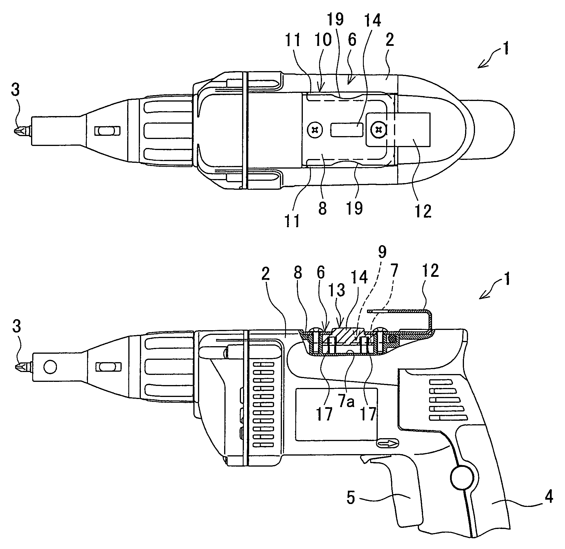
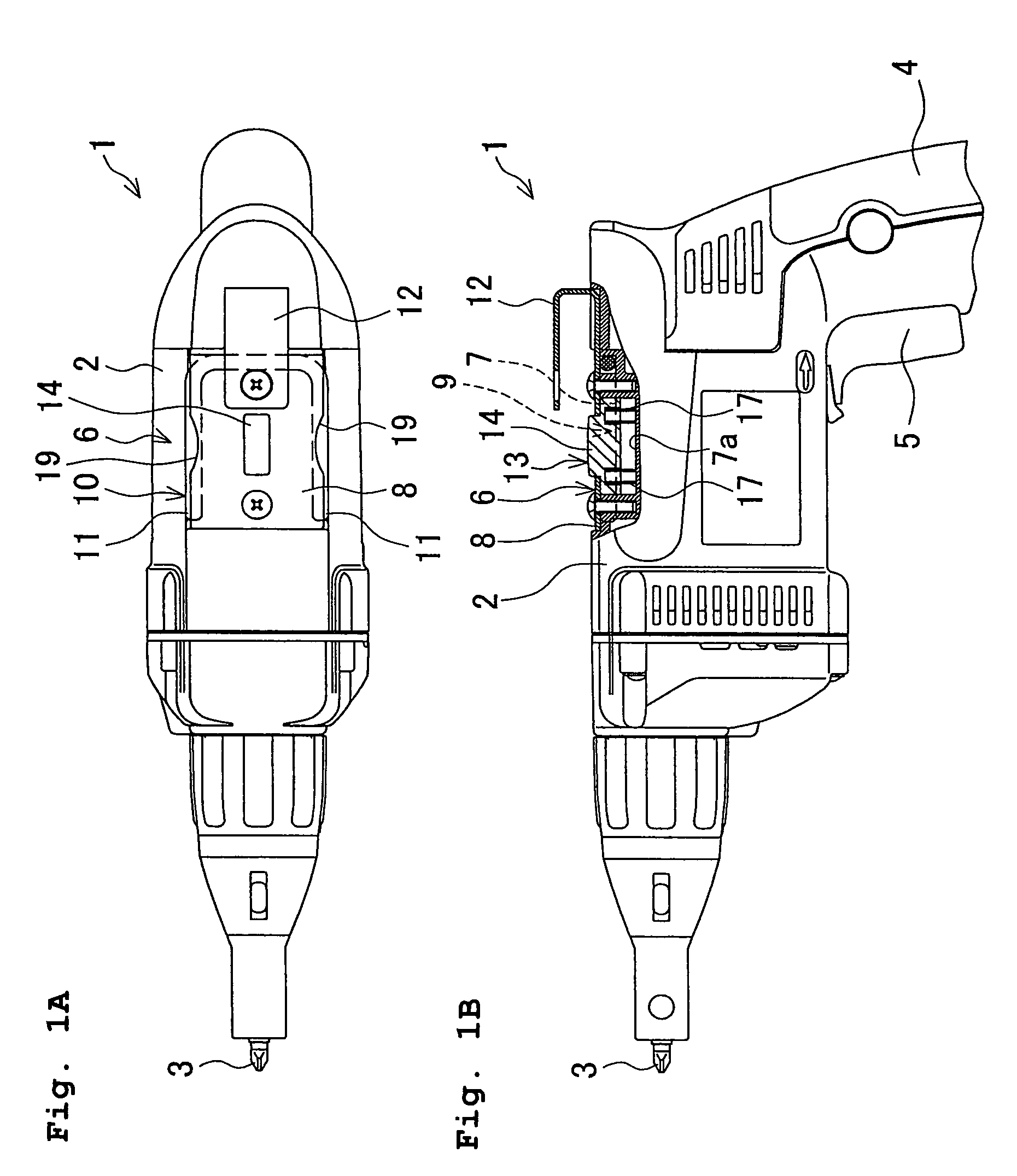
[0031]A power screwdriver 1 shown in FIGS. 1A and 1B is one example of a power tool with a hook structure consistent with the present invention. The power screwdriver 1 is of a type known in the art, and has electric power elements (not shown), such as a motor, a rotation transmission mechanism and a torque limiter, incorporated in a housing 2, to produce and transmit the torque to a screwdriver bit 3 held at a front end (left-hand end in FIGS. 1A and 1B) of the power screwdriver 1. At the rear of the housing 2 of the power screwdriver 1, a grip 4 extending therefrom and having a trigger switch 5 is provided.

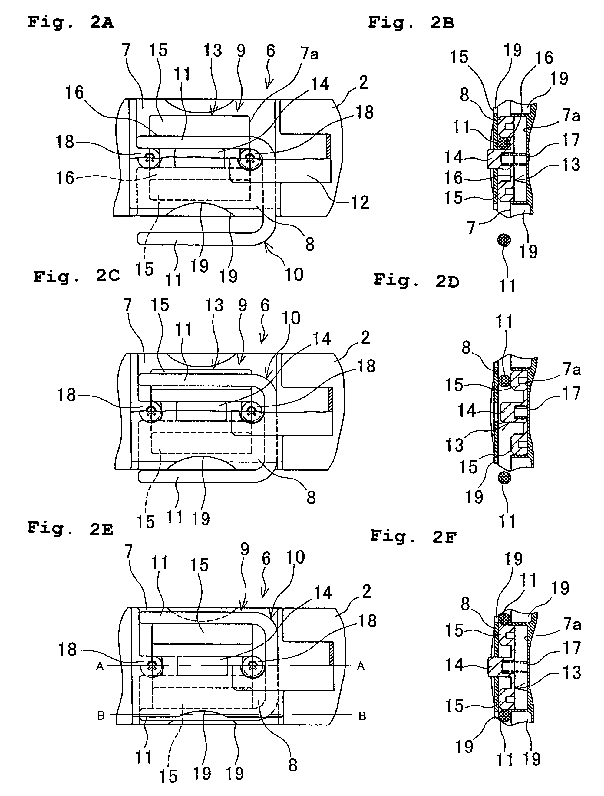
[0032]At an upper surface of the housing 2, a hook unit 6 is provided as a hook structure according to a first embodiment of the present invention. The hook unit 6 includes a hook-receiving portion 9 provided in the housing 2 with openings facing leftward and rightward, and a substantially U-shaped hook 10 having two legs 11 which are a left hook leg 11 and a right hook leg 11. ...

second embodiment

[0039]The first embodiment described above exemplifies a hook structure in which one and the same hook can be used at either of the left or right side of the power screwdriver 1, selectively. It is however appreciated that the same hook can also be used at the upper side of the power screwdriver 1 in some modified arrangements. According to a second embodiment of the present invention, one example of such a hook structure is shown as a hook unit 6a in FIG. 4A in which the same elements as in the first embodiment are designated by the same reference numerals, and a duplicate explanation will be omitted in describing the second embodiment.

[0040]This hook unit 6a has no upper hook fixed on the upper plate 8. In the housing 2, a depression 20 is provided at a front side of the recess 7. The depression 20 is recessed in alignment with an imaginary extension line extending frontward from the right groove 11 formed on the right side of the lock button 13 located in the upper-limit position...

third embodiment

[0046]A description will now be given of a third embodiment which offers a selection of angles of upward protrusion of a hook. In a hook unit 6b shown in FIGS. 5A and 5B, a lock button 13 includes an operation part 14 and a locking element 15 provided on the right side of the operation part 14, and a groove 16 formed between the operation part 14 and the locking element 15 is disposed in a center of the hook-receiving portion 9. A depression 20, a coil spring 21 and a lid 22 are disposed in alignment with an imaginary extension line extending frontward from the groove 16 when the lock button 13 is located in the upper-limit position. Moreover, in the hook-receiving portion 9, a constraint block 26 is provided over a left area of a recess 7 to block up the left side of the operation part 14, with a space left at a left side of the constraint block 26, so as to allow the left hook leg 11 to be fitted on the constraint block 26 within the space. The constraint block 26 is also used as ...


PUM


Abstract

In a housing of a power tool is formed a hook-receiving portion, with openings facing leftward and rightward, through which a substantially U-shaped hook having a left hook leg and a right hook leg is movable among a left protruding position in which the left hook leg protrudes leftward from the hook-receiving portion, a right protruding position in which the right hook leg protrudes rightward from the hook-receiving portion, and an accommodating position in which the left and right hook legs are both accommodated in the hook-receiving portion. Also provided in the housing is a retaining mechanism by which the hook is retainable in one of the positions of the left protruding position, right protruding position, and accommodating position.

Description

BACKGROUND OF THE INVENTION[0001]This application claims the entire benefit of Japanese Patent Application Numbers 2007-194956 filed on Jul. 26, 2007 and 2008-27947 filed on Feb. 7, 2008, the entirety of which is incorporated by reference.FIELD OF THE INVENTION[0002]This invention relates to a hook structure of a power tool for making the power tool suspensible.DESCRIPTION OF RELATED ART[0003]It is not uncommon to find a power tool having a hook or a hook-shaped structure with which the power tool can be suspended on an engageable portion provided on a wall, a belt of an operator, or the like. The hook may be a nuisance during performance of work due to its protrusion unless it is retractable. For this reason, the power tool may have a housing provided with a hook-receiving portion into which the hook can be retracted when the hook is not in use, as described for example in Japanese Patent No. 3676609 (JP 3676609 B2).[0004]Meanwhile, the power tool suspensible on the belt of an oper...

Claims


Application Information

Patent Timeline
Patent Type & Authority Patents(United States)
IPC IPC(8): B25B29/00
CPCB25F5/02
Inventor SHIBATA, YOSHINORIUKAI, TOMOHIRO
Owner MAKITA CORP
Why Eureka
Try Eureka