Thin film magnetic head having heating element

a technology of heating element and thin film, which is applied in the direction of maintaining the head carrier alignment, metal sheet core head, instruments, etc., can solve the problems of easy electromigration, easy collision of thin film magnetic head with recording medium, and increase in the amount of protrusion of the surface facing the recording medium

Active Publication Date: 2007-01-25
TDK CORPARATION
View PDF7 Cites 25 Cited by
  • Summary
  • Abstract
  • Description
  • Claims
  • Application Information

AI Technical Summary

Problems solved by technology

Consequently, the amounts of thermal expansion of the magnetic gap, the core layer, and the like vary, resulting in an increase in the fluctuation in the amount of protrusion of the surface facing the recording medium.
In the worst case, if the amount of protrusion of the surface facing the recor

Method used


Image

  • Thin film magnetic head having heating element
  • Thin film magnetic head having heating element
  • Thin film magnetic head having heating element

Examples


Embodiment Construction

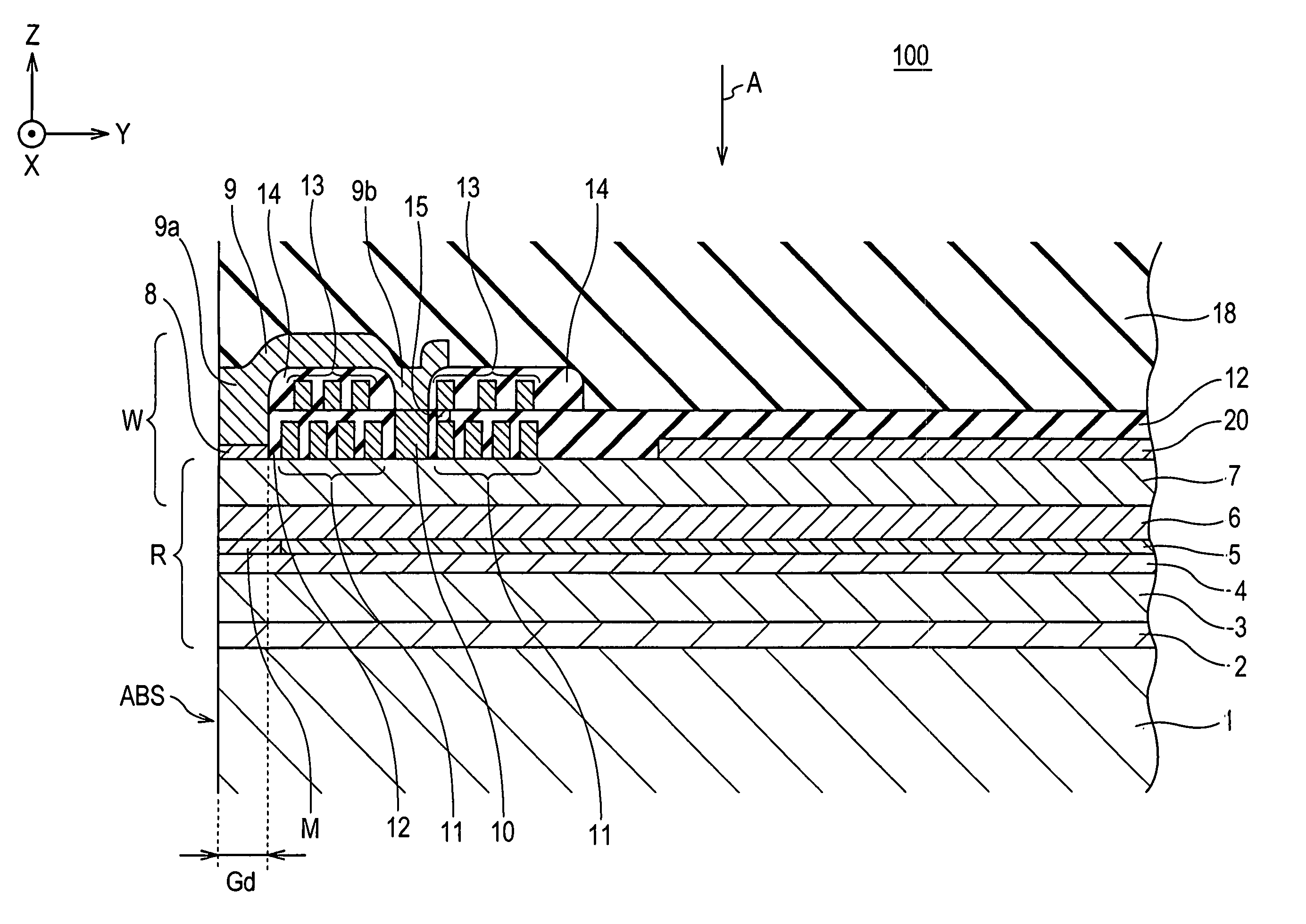
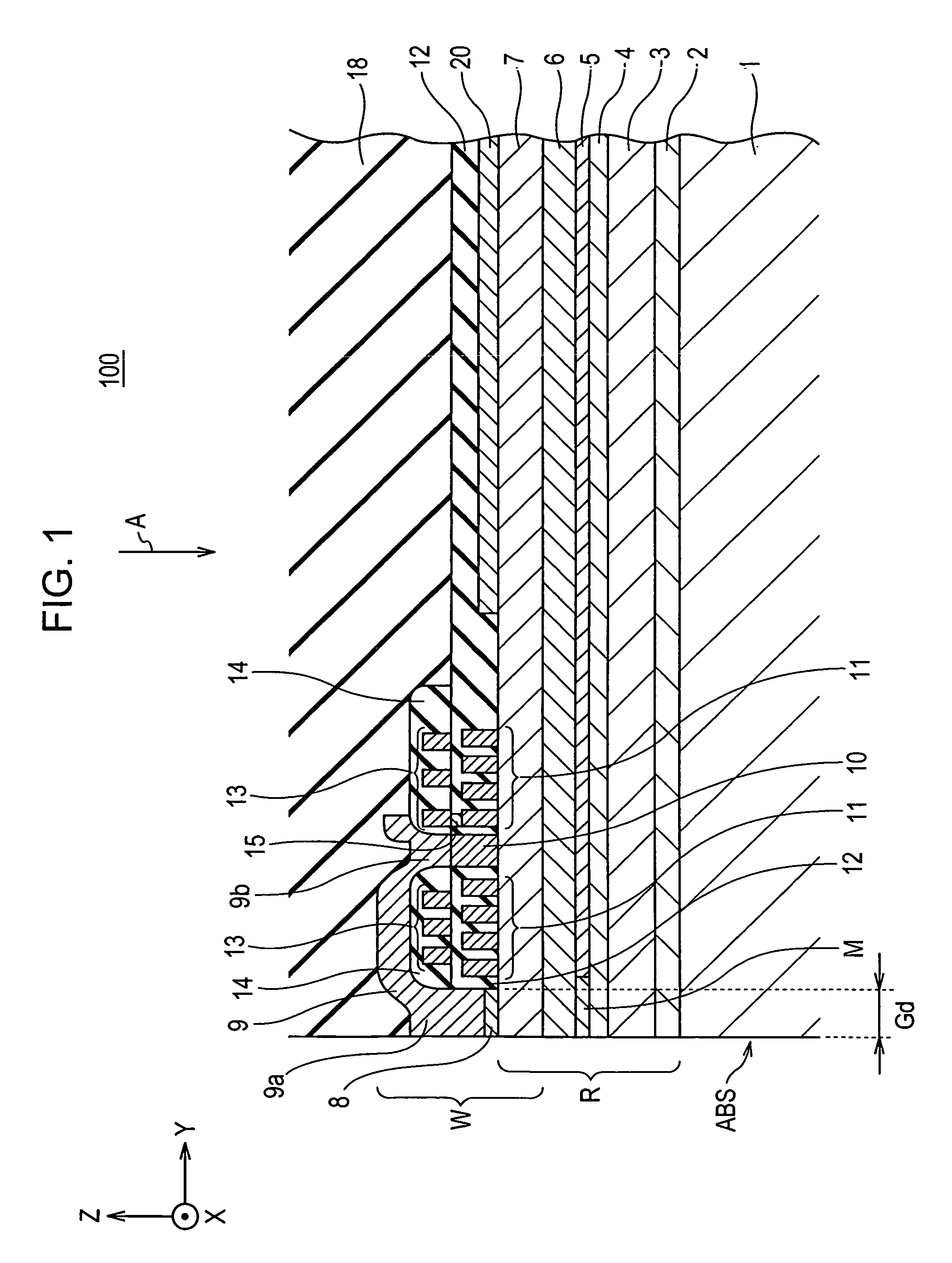
[0076] In each experiment, a heating element 20 shown in FIG. 4 was formed and the heating element 20 was incorporated into a thin film magnetic head shown in FIG. 1. Then, the relationship between the current application time and the rate of change in resistance of the heating element 20 was examined. In the experiment shown in each of FIGS. 11 to 14, the environmental temperature was set at 20° C. and the current was set at 40 mA.

[0077] Herein, the term “rate of change in resistance” is defined as a ratio of a change from a reference resistance to the reference resistance, the reference resistance being the resistance of the heating element 20 at a current application time of 0. That is, the rate of change in resistance (%) is equal to [(resistance (x)−reference resistance) / reference resistance]×100, wherein the resistance (x) is the resistance of the heating element 20 at a current application time of x.

[0078]FIG. 11 shows the experimental results when the heating element 20 wa...


PUM


Abstract

A thin film magnetic head is provided. The thin film magnetic head includes a read head and a write head, a heating element, or the combination thereof. The heating element includes a heating conductor layer and a high-melting-point-material layer disposed so as to at least partially overlap the heating conductor layer. Electromigration in the heating conductor layer can be suppressed.

Description

[0001] This application claims the benefit of Japanese Patent Application No. 2005-210073 filed on Jul. 20, 2005, which is hereby incorporated by reference. BACKGROUND [0002] 1. Field [0003] A thin film magnetic head in which the surfaces of a read head and a write head facing a recording medium protrude toward the recording medium by means of thermal expansion is provided. [0004] 2. Related Art [0005] Japanese Unexamined Patent Application Publication Nos. 2005-11413, 2005-11414, and 2003-168274 (Patent Documents 1 to 3) each propose a thin film magnetic head that includes a heating element provided therein and in which the magnetic gap and its vicinity are thermally expanded and the surface facing a recording medium is allowed to protrude toward the recording medium so that the floating height of the thin film magnetic head can be decreased. Japanese Unexamined Patent Application Publication No. 10-261248 (Patent Document 4) also discloses a related technique. [0006] In order to a...

Claims


Application Information

Patent Timeline
IPC IPC(8): G11B5/147
CPCG11B5/3133G11B5/6064G11B5/6005
Inventor SHIMIZU, YOSHIAKITAKAHASHI, AKIRA
Owner TDK CORPARATION
Why Eureka
Try Eureka