
System for controlling contact location during TFC touchdown and methods thereof

a technology of contact location and touchdown, applied in the field of data storage systems, can solve the problems of device malfunction or erratically operating, failure to provide the absolute spacing of the reader from the disk, crash or loss of data, etc., and achieve the effect of reducing thermal protrusion

Active Publication Date: 2012-04-03
WESTERN DIGITAL TECH INC
View PDF20 Cites 25 Cited by
  • Summary
  • Abstract
  • Description
  • Claims
  • Application Information

AI Technical Summary

Benefits of technology

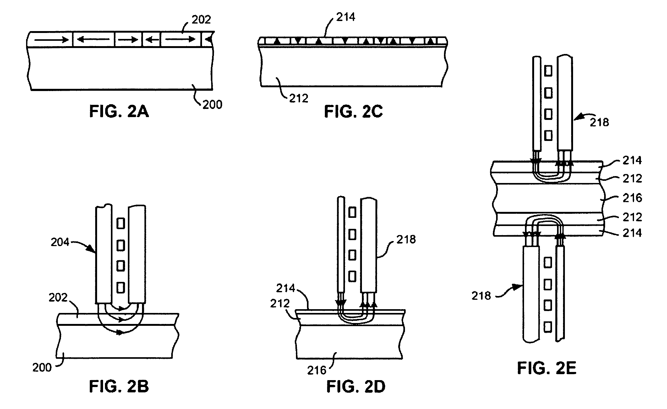
The patent describes a system and method for calibrating the protrusion of a magnetic head. The system includes a thin film stack with a magnetic transducer and a contact pad, and a heater that induces thermal protrusion of the thin film stack. The thin film stack is characterized by the contact pad protruding farther than the magnetic transducer upon heating. The method involves increasing the thermal protrusion of the magnetic head to induce head-medium contact, determining that the head has contacted the medium, and storing parameters for inducing a desired amount of protrusion based on the determination. The technical effect of this patent is to provide a reliable and efficient way to calibrate the protrusion of a magnetic head for optimal performance in recording and reading data on magnetic media.

Problems solved by technology

Unfortunately, this conventional method of TFC, which is now commonly used to control the slider disk spacing in head disk drives, does not provide the absolute spacing of the reader from the disk, as the contact location can be away from the reader.
The AlTiC is much harder than the disk, and therefore damage to the disk overcoat or the disk itself may result from contact and create a risk of disk corrosion or defective sites that may cause a crash or loss of data.
Also, contact between the reader or writer pole-tip and the hard disk can damage the reader / writer and cause performance issues due to magnetostriction or may cause the device to malfunction or operate erratically.
Similarly, contact with the reader / writer may cause the carbon overcoat to wear off, possibly leading to corrosion of the head.

Method used

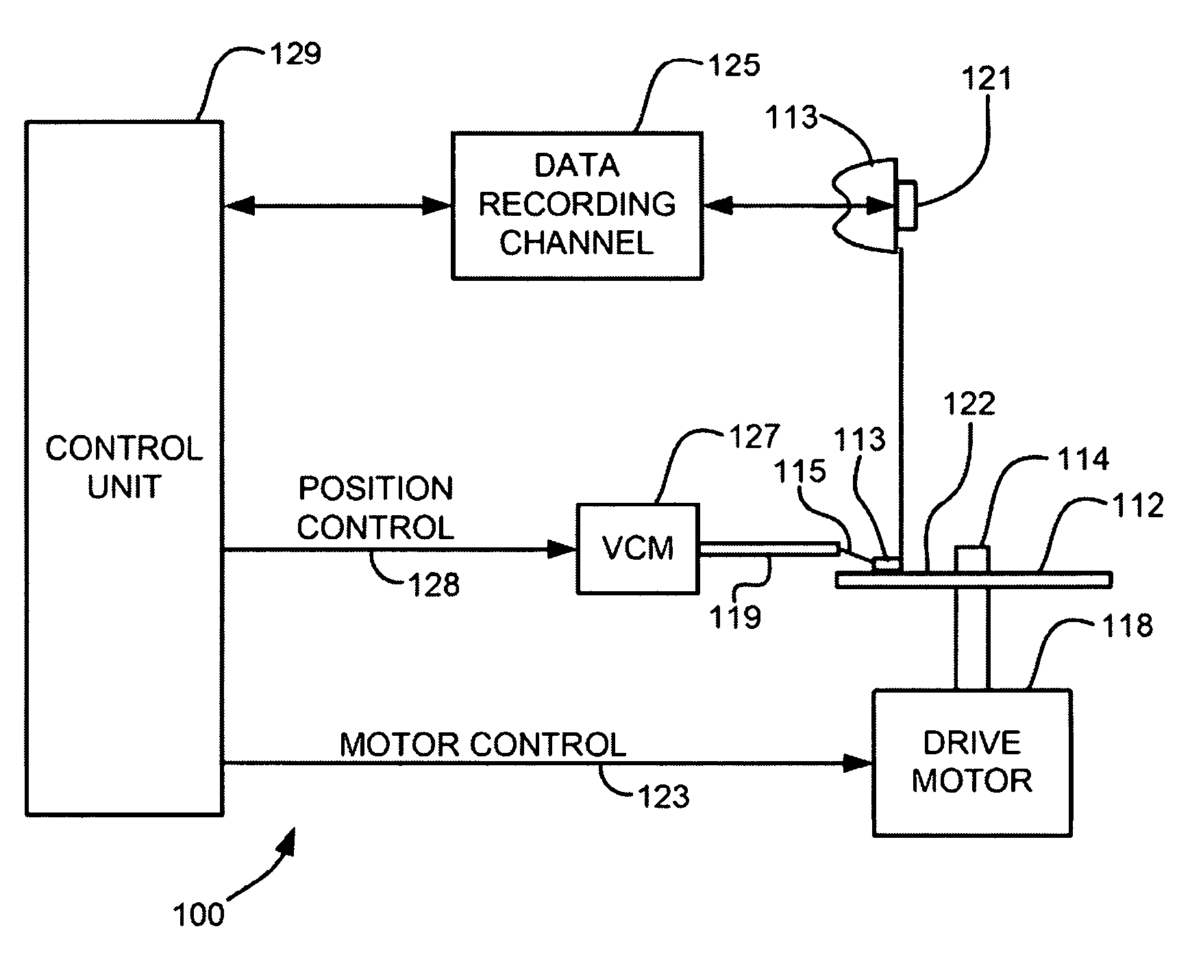

Image

  • System for controlling contact location during TFC touchdown and methods thereof
  • System for controlling contact location during TFC touchdown and methods thereof
  • System for controlling contact location during TFC touchdown and methods thereof

Examples


Embodiment Construction

[0028]The following description is made for the purpose of illustrating the general principles of the present invention and is not meant to limit the inventive concepts claimed herein. Further, particular features described herein can be used in combination with other described features in each of the various possible combinations and permutations.

[0029]Unless otherwise specifically defined herein, all terms are to be given their broadest possible interpretation including meanings implied from the specification as well as meanings understood by those skilled in the art and / or as defined in dictionaries, treatises, etc.

[0030]It must also be noted that, as used in the specification and the appended claims, the singular forms “a,”“an” and “the” include plural referents unless otherwise specified.

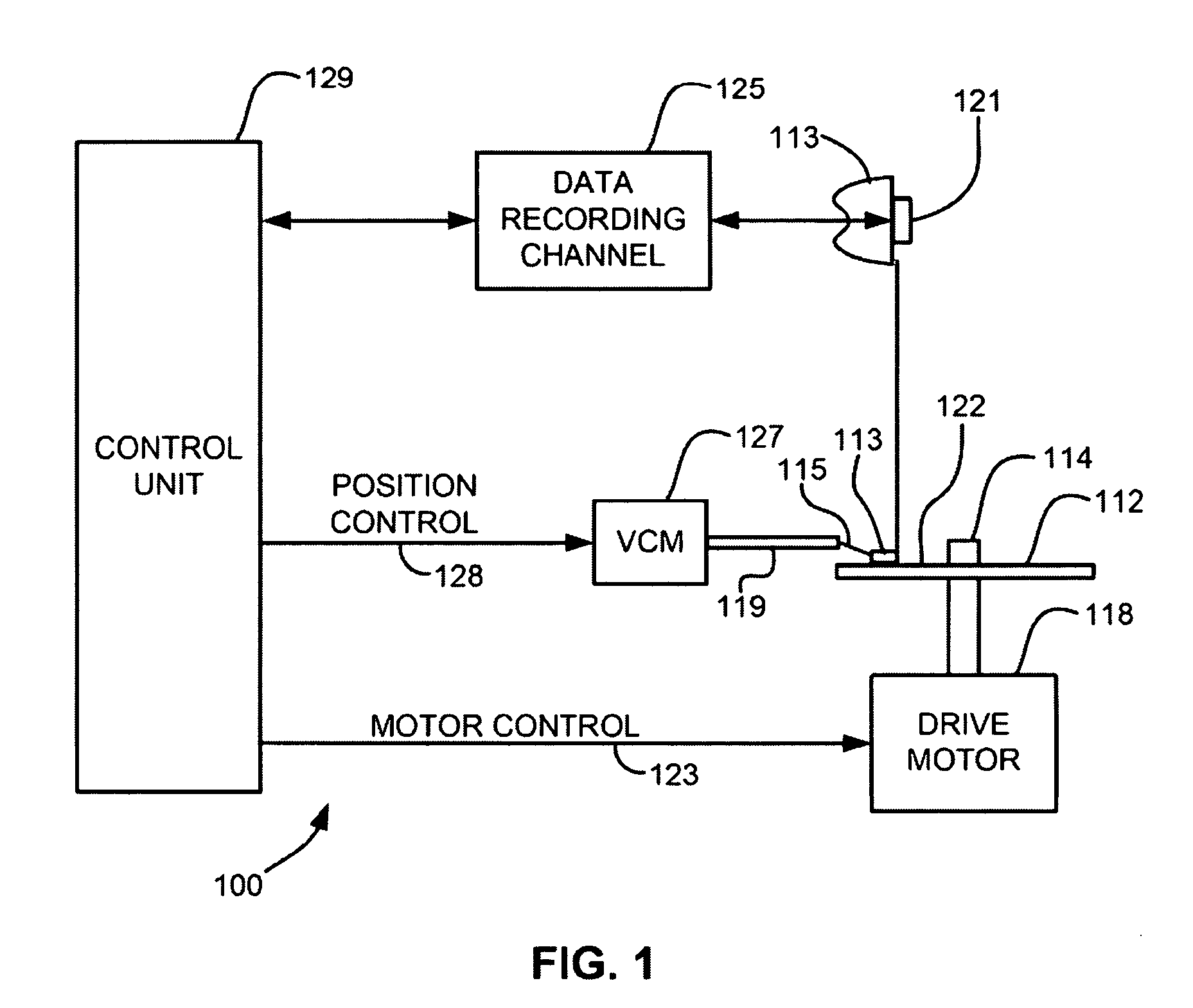
[0031]The following description discloses several preferred embodiments of disk-based storage systems and / or related systems and methods, as well as operation and / or component parts thereof.

[00...


PUM

PropertyMeasurementUnit
corrosion resistantaaaaaaaaaa
coefficient of thermal expansionaaaaaaaaaa
thermal protrusionaaaaaaaaaa

Abstract

A system according to one embodiment includes a thin film stack having a magnetic transducer and a contact pad; and a heater in the thin film stack for inducing thermal protrusion of a media-facing side of the thin film stack, wherein the thin film stack is characterized by the contact pad protruding farther than the magnetic transducer upon the thin film stack being heated by the heater. A method for calibrating a protrusion of a magnetic head includes increasing a thermal protrusion of a magnetic head to induce head-medium contact; determining that the head has contacted the medium, wherein a portion of the head that contacts the medium is a contact pad or overcoat of the contact pad; determining parameters for inducing a desired amount of protrusion based in part on the determination that the head has contacted the medium; and storing the parameters.

Description

FIELD OF THE INVENTION[0001]The present invention relates to data storage systems, and more particularly, this invention relates to controlling the contact location during thermal fly-height control touchdown in magnetic disks.BACKGROUND OF THE INVENTION[0002]The heart of a computer is a magnetic disk drive which typically includes a rotating magnetic disk, a slider that has read and write heads, a suspension arm above the rotating disk and an actuator arm that swings the suspension arm to place the read and / or write heads over selected circular tracks on the rotating disk. The suspension arm biases the slider into contact with the surface of the disk when the disk is not rotating but, when the disk rotates, air is swirled by the rotating disk adjacent an air bearing surface (ABS) of the slider causing the slider to ride on an air bearing a slight distance from the surface of the rotating disk. When the slider rides on the air bearing the write and read heads are employed for writin...

Claims


Application Information

Patent Timeline
Patent Type & Authority Patents(United States)
IPC IPC(8): G11B5/60
CPCG11B5/6005G11B5/6064
Inventor BAUMGART, PETER MICHAELJUANG, JIA-YANGSINGH, GURINDER PAL
Owner WESTERN DIGITAL TECH INC
Learn More