
Flat cable and connection structure between flat cable and printed wiring board

a technology of flat cable and printed wiring board, which is applied in the direction of connection, fixed connection, coupling device connection, etc., can solve the problems of plastic reinforcement plate not having enough rigidity, impeding the downsizing of the connecting portion, and the elastic deformation force of the flat wiring material restricting the clip gradually deteriorating, so as to improve the rigidity of the reinforcing member. , the effect of improving the rigidity

Inactive Publication Date: 2012-11-13
HITACHI CABLE
View PDF8 Cites 1 Cited by
  • Summary
  • Abstract
  • Description
  • Claims
  • Application Information

AI Technical Summary

Benefits of technology

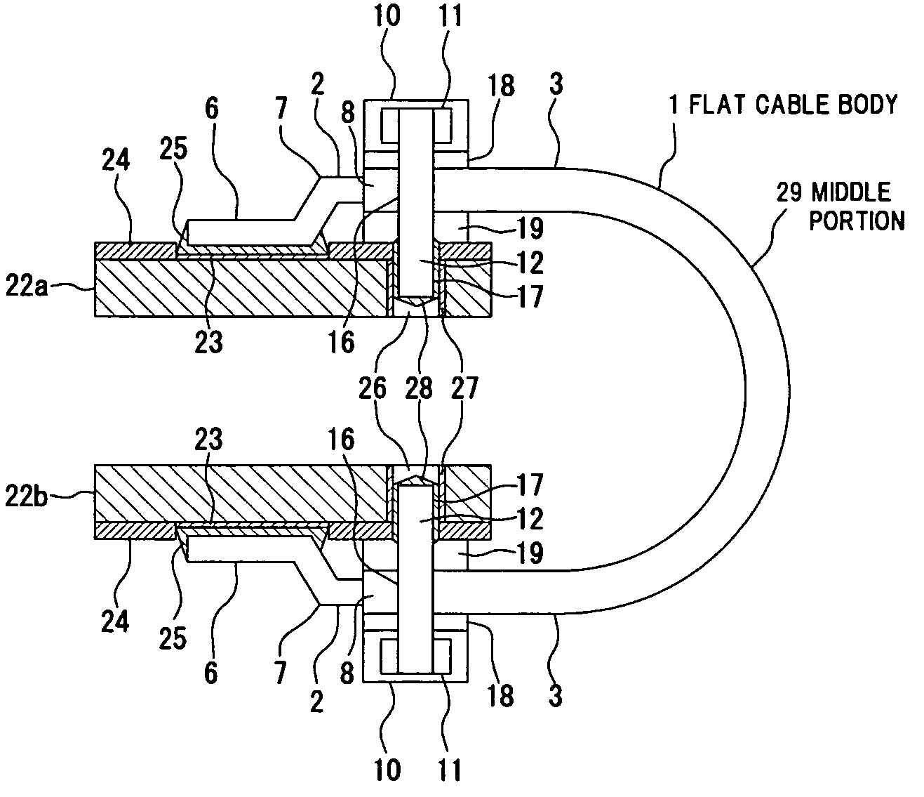
"The invention provides a flat cable and a connection structure between a flat cable and a printed wiring board that can ensure stable connection reliability against mechanical load such as vibration for long time or impact without causing fracture or damage to the connecting portion. The flat cable includes a plurality of conductors arranged in parallel and exposed at both end portions in a longitudinal direction thereof, an insulation film covering the conductors except the exposed both end portions, and a reinforcing member that covers the plurality of conductors along a width direction of the conductors and is fixed to an external printed wiring board or inserted into a through-hole in the external printed wiring board. The reinforcing member includes a metal plate and an insulative covering layer for covering the metal plate and is designed to protect the connecting portion from damage."

Problems solved by technology

There is a concern that the elastic deformation force of the flat wiring material restricting clip gradually deteriorates due to mechanical load such as vibration which is repeatedly applied for long term.
It is believed that an external mechanical force in a separating direction which acts on the connecting portion of the flat wiring material is gradually increased due to deterioration in the elastic deformation force, i.e., restricting force, leading to damage at some stage.
Meanwhile, the structure described in JP-A-8-203577 is to reinforce by covering the connecting portion together with the flat cable and the printed wiring board, hence, an area for providing the reinforcing member becomes larger than the width of the flat cable or the width of the printed wiring board, which is a cause of impeding the downsizing of the connecting portion.
It is anticipated that the plastic reinforcement plate does not have enough rigidity against mechanical load when being mounted on an on-vehicle device, and a sufficient load suppression effect may not be obtained.
Furthermore, in the means described in JP-A-2002-216873, it is anticipated that looseness occurs at a fixed portion between the screw or the terminal having a claw formed at a tip thereof and the printed wiring board due to the mechanical load such as vibration which is repeatedly applied for long term.
The looseness lowers the restricting force of the fixing board and increases the external mechanical force acting on the connecting portion of the cable conductor, which may lead to damage to the conductor of the cable.

Method used


Image

  • Flat cable and connection structure between flat cable and printed wiring board
  • Flat cable and connection structure between flat cable and printed wiring board
  • Flat cable and connection structure between flat cable and printed wiring board

Examples


embodiment

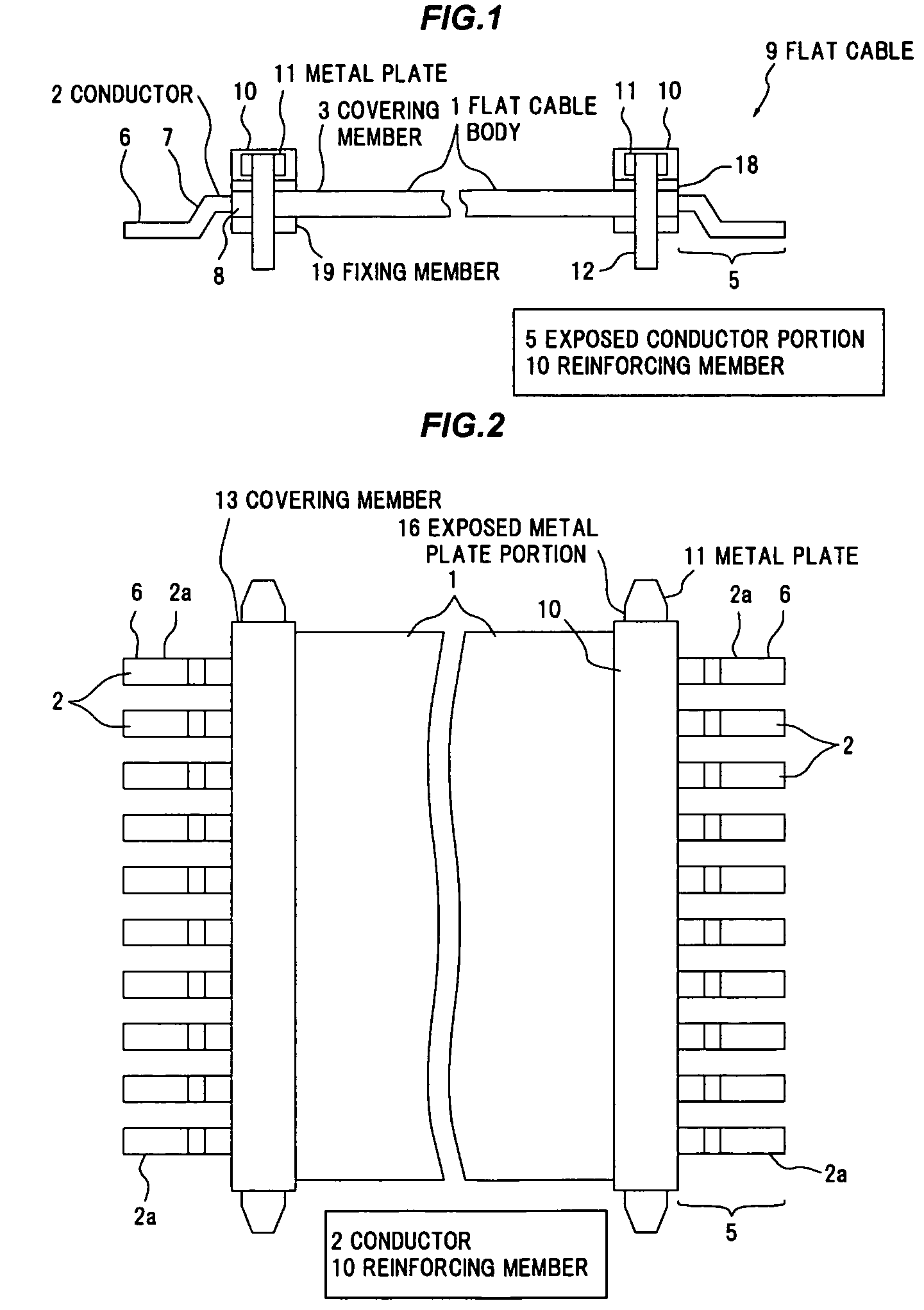
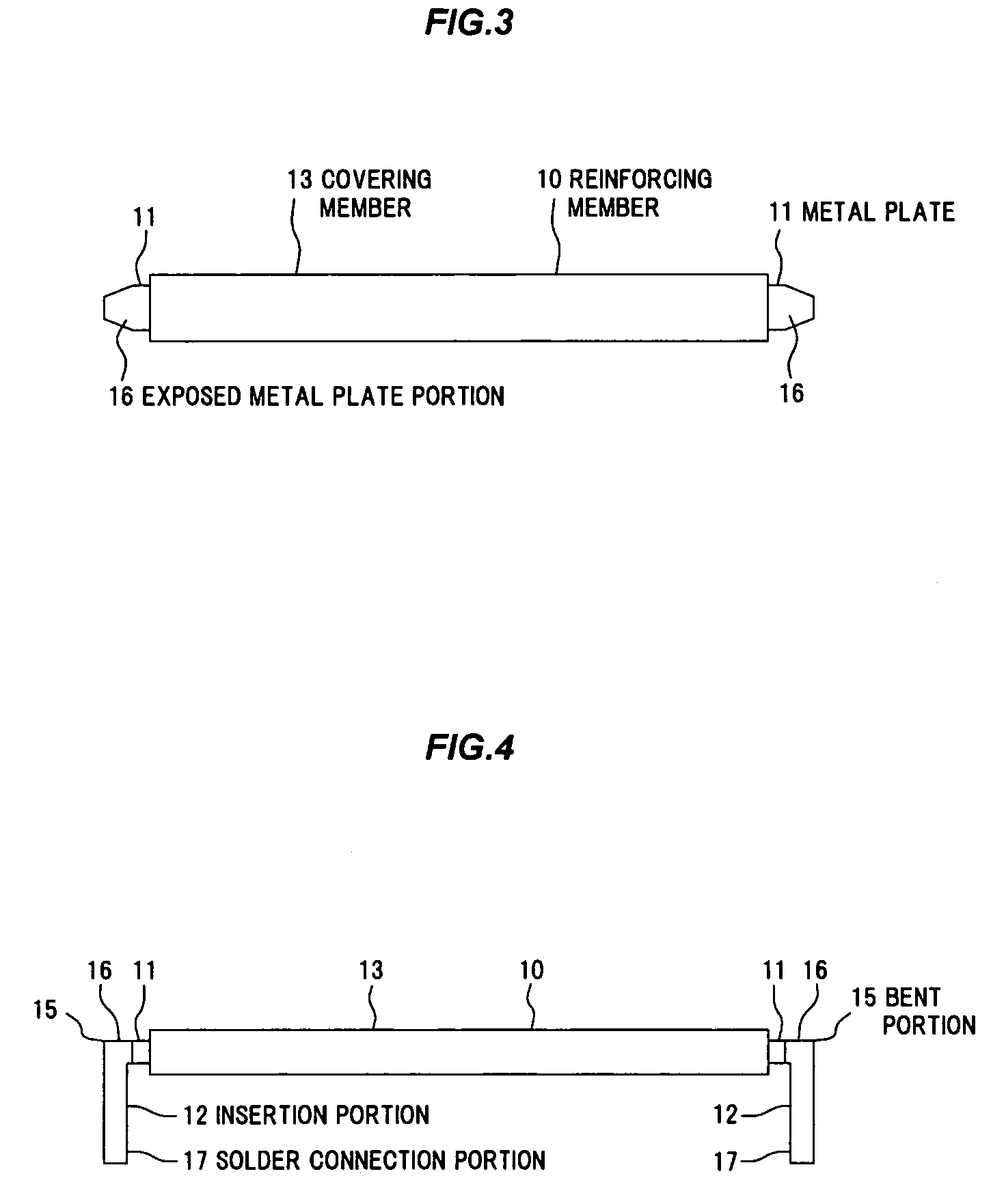
[0067]FIG. 1 is a schematic side view showing a flat cable provided with a reinforcing member and a fixing member in the present embodiment and FIG. 2 is a schematic plan view showing the flat cable shown in FIG. 1. FIG. 3 is a schematic plan view showing a reinforcing member constituting the flat cable shown in FIG. 1 and FIG. 4 is a side view showing the reinforcing member shown in FIG. 3. FIG. 5 is a schematic partial cross sectional view showing an inner structure of the reinforcing member shown in FIG. 3. FIG. 6 is a partial cross sectional view showing the inner structure of the flat cable. FIGS. 7A to 7D are partial enlarged side views showing a solder connection portion of the flat cable shown in FIG. 1.

[0068]Firstly, as shown in FIG. 1, a flat cable 9 in the present embodiment is provided with a flat cable body 1, a reinforcing member 10 for reinforcing the flat cable body 1 at the vicinity of both longitudinal end portions of the flat cable body 1, and a fixing member 19 a...


PUM


Abstract

A flat cable includes a plurality of conductors arranged in parallel and exposed at both end portions in a longitudinal direction thereof, an insulation film covering the plurality of conductors except the exposed both end portions, and a reinforcing member that covers the plurality of conductors along a width direction of the plurality of conductors, is provided on a surface of the insulation film in a part of a region including an edge of the insulation film, and includes a metal plate and an insulative covering layer for covering the metal plate.

Description

[0001]The present application is based on Japanese Patent Application No. 2011-005105 filed on Jan. 13, 2011, the entire contents of which are incorporated herein by reference.BACKGROUND OF THE INVENTION[0002]1. Field of the Invention[0003]The invention relates to a flat cable, and a connection structure between a flat cable and a printed wiring board.[0004]2. Description of the Related Art[0005]Conventionally, a wire harness is used as a wiring component for electrically connecting plural printed wiring boards which are mounted inside an on-vehicle inverter unit or an engine control unit, etc., and a connection structure using a connector component is employed for connection between the wire harness and the printed wiring board. In recent years, use of an alternative wiring component in place of wire harness, an application of a connection method not using a connector component and simplification of connection process are required as a measure of realizing both downsizing / thinning ...

Claims


Application Information

Patent Timeline
Patent Type & Authority Patents(United States)
CPCH01R12/53H01R12/79
Inventor YAGUCHI, AKIHIROKOBAYASHI, TAKUMIMURAKAMI, KENICHIKOMATSU, HIROAKI
Owner HITACHI CABLE
Learn More