
Method for rotating a vertebra or vertebrae

a technology for rotating vertebrae and vertebrae, which is applied in the field of rotating vertebrae or vertebrae, can solve the problems of reducing the precision of stress applied, reducing the accuracy of stress applied, and reducing the risk of fracture of vertebrae,

Active Publication Date: 2012-11-13
MEDICREA INT SA
View PDF18 Cites 23 Cited by
  • Summary
  • Abstract
  • Description
  • Claims
  • Application Information

AI Technical Summary

Benefits of technology

[0004]An object of the invention is to provide a novel method of rotating one or more vertebra without inducing a risk of weakening of the anchoring of the screws fixed to the vertebrae or of rupture of the vertebrae.

Problems solved by technology

However, this technique has the disadvantage of exerting great transverse stress on screws attached to the vertebrae, inducing a risk of weakening of the anchoring of these screws in the vertebrae, or even ruptures of the vertebrae.
Moreover, the surgeon has difficulty precisely evaluating the amount of stress applied.

Method used


Image

  • Method for rotating a vertebra or vertebrae
  • Method for rotating a vertebra or vertebrae
  • Method for rotating a vertebra or vertebrae

Examples


Embodiment Construction

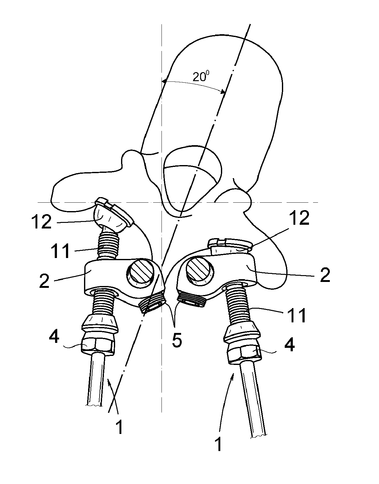
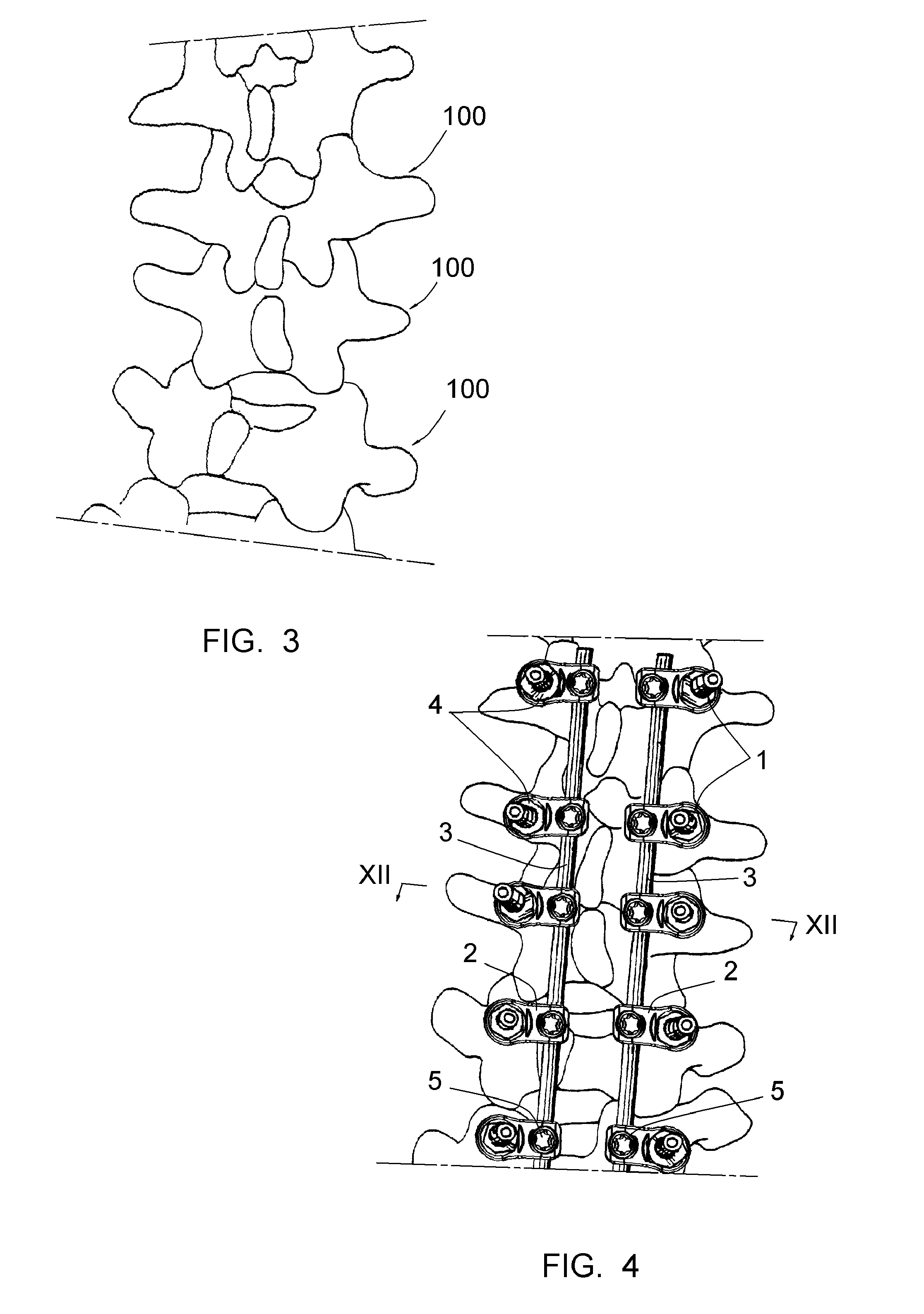
[0021]FIG. 4 shows a device usable in the method of the present invention to rotate a vertebra or vertebrae, the device including polyaxial screws 1, clamping parts 2, linking rods 3, tightening nuts 4, and set screws 5.

[0022]In some embodiments, the polyaxial screws 1, linking rods 3 and tightening nuts 4 may be as described in U.S. Pat. No. 6,267,765, the contents of which are incorporated herein by reference. As disclosed in this document and as shown on FIG. 5, each of the polyaxial screws 1 has an anchoring distal part intended to be anchored to a pedicle of a vertebrae 100 and a bearing portion 12 articulated with respect to the anchoring distal part. The anchoring distal part has a threaded portion 11 on a proximal part.

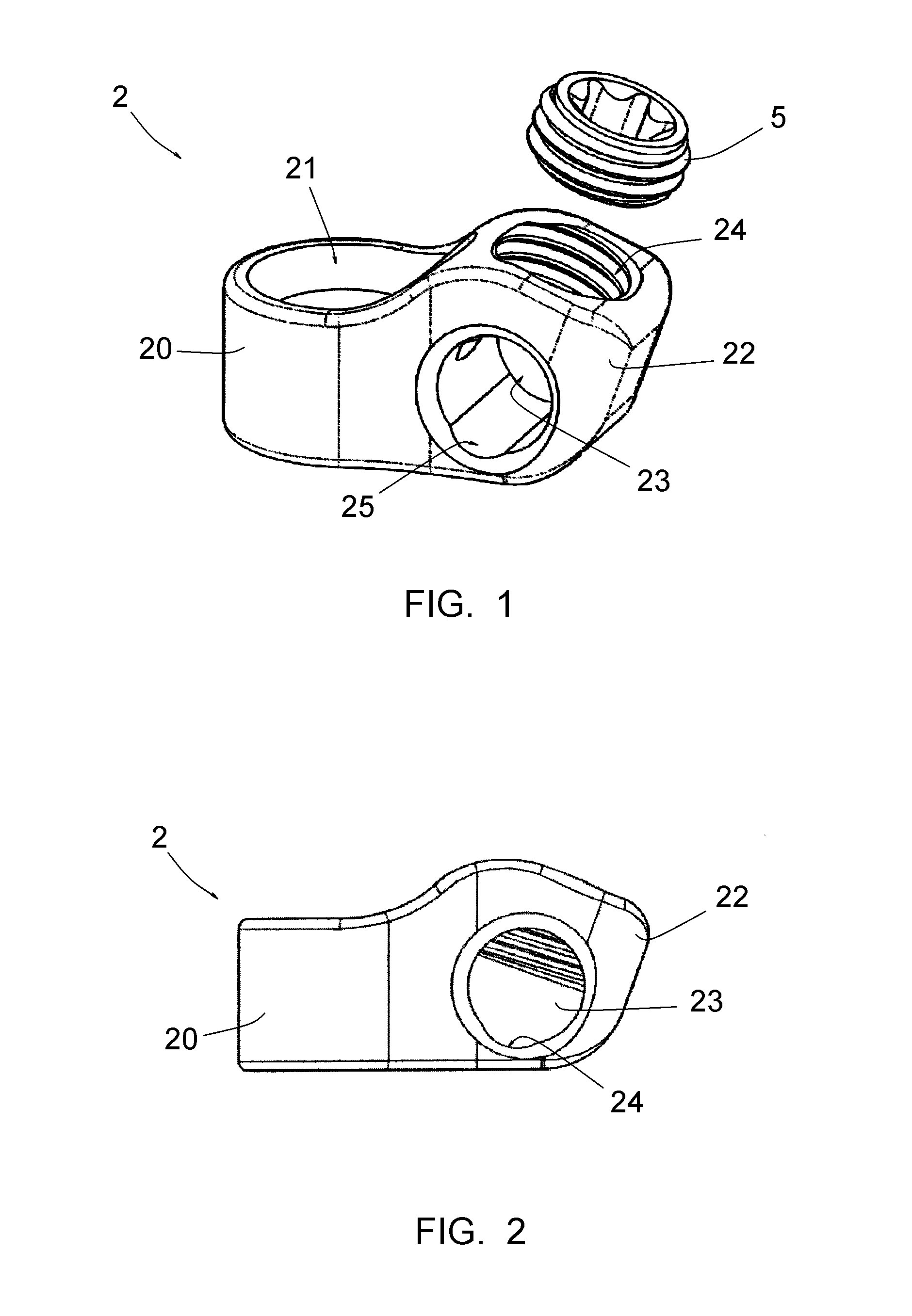
[0023]With reference now to FIGS. 1 and 2, each of the clamping parts 2 in a preferred embodiment includes a first part 20 delineating a first hole 21 for engagement on the threaded portion 11 of one of the polyaxial screws 1 and a second part 22 delineating a...


PUM


Abstract

A method for rotating a vertebra or vertebrae in a spine that is curved using a vertebral osteosynthesis device that includes polyaxial screws, linking rods, clamping parts, tightening nuts, and set screws. The method includes the steps of: implanting two series of the screws, clamping parts, and linking rods; completely tightening the tightening nuts of a first series of screws on the convex side of the spine curvature; completely tightening the set screws of a second series of screws on the concave side of the spine curvature; tightening the tightening nuts of the second series; and tightening the set screws of the first series.

Description

[0001]This application claims priority from U.S. Provisional Application 61 / 105,334 filed Oct. 14, 2008, which is incorporated by reference.BACKGROUND OF THE INVENTION[0002]It is known to correct deformations of the spine, such as scoliosis or kyphosis, in the frontal plane and / or the sagittal plane. Generally, a correction in a transverse plane (i.e., a plane perpendicular to the axis of the spine) is not carried out, although such a correction may also be desirable.[0003]When a correction in the transverse plane is required, it is known to use a vertebrae adjusting device to exert a torque on the vertebrae and to maintain the vertebrae in the corrected position until the vertebrae are fixed with vertebral fixing equipment including anchoring screws and linking rods. However, this technique has the disadvantage of exerting great transverse stress on screws attached to the vertebrae, inducing a risk of weakening of the anchoring of these screws in the vertebrae, or even ruptures of ...

Claims


Application Information

Patent Timeline
Patent Type & Authority Patents(United States)
IPC IPC(8): A61B17/88
CPCA61B17/8866A61B17/7041
Inventor CLEMENT, JEAN-LUCFIERE, VINCENT
Owner MEDICREA INT SA
Learn More