Apparatus for splitting signal and video device using the same

a technology of video device and signal, which is applied in the field of apparatus for splitting signal and video device, can solve the problems of signal processing errors, increased noise figure (nf), and increased nf of broadcast signals

Inactive Publication Date: 2012-11-13
SAMSUNG ELECTRONICS CO LTD
View PDF17 Cites 0 Cited by
  • Summary
  • Abstract
  • Description
  • Claims
  • Application Information

AI Technical Summary

Benefits of technology

[0009]Another object of the present invention is to an apparatus for splitting a signal, which splits an inputted broadcast signal without using an active element, such as an amplifier or the like, thereby allowing split broadcast signals to lower a NF thereof and to uniformly maintain a gain thereof, and a video device using the same.
[0010]Still another object of the present invention is to an apparatus for splitting a signal capable of preventing interferences, which are generated between adjacent ports, and a video device using the same.
[0016]The isolating element may block a leakage of at least one of the first and the second broadcast signal processing elements from exerting influence on at least one of the third and the fourth broadcast signal processing elements.

Problems solved by technology

Since the four broadcast signals formed as described above are formed after passing splitting processes of total two times, a problem occurs, in that they have noise figure (NF) increased.
However, since such amplifiers belong to the active element, with use of the amplifiers, a problem occurs, in that, the NF of the broadcast signals is increased all the more.
Accordingly, a problem occurs, in that broadcast signal processing elements, which require a certain gain of broadcast signals, generate errors in signal processing.
Also, if a port from which one split broadcast signal is outputted is located adjacent to a port from which another split broadcast signal is outputted, a leakage generated from one split broadcast signal has an effect on another split broadcast signal, thereby deteriorating the performance of the signal splitting apparatus.

Method used


Image

  • Apparatus for splitting signal and video device using the same
  • Apparatus for splitting signal and video device using the same
  • Apparatus for splitting signal and video device using the same

Examples


Embodiment Construction

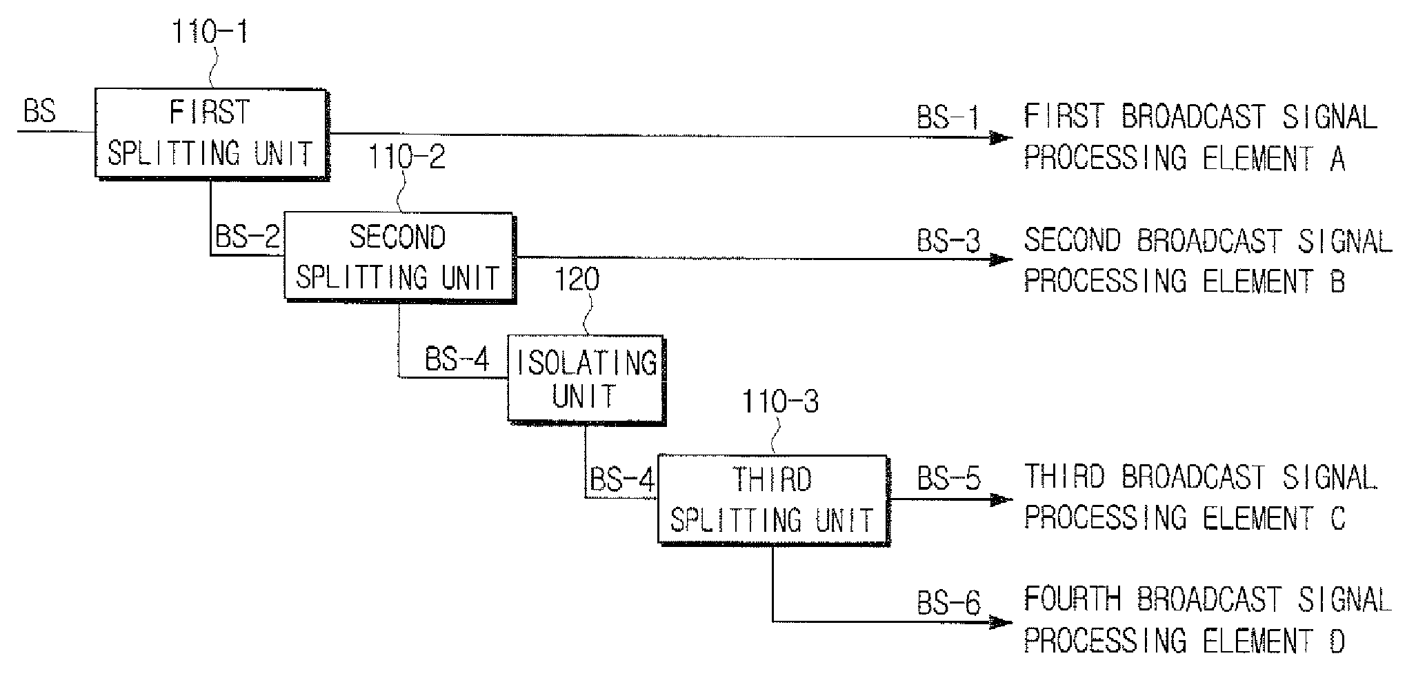
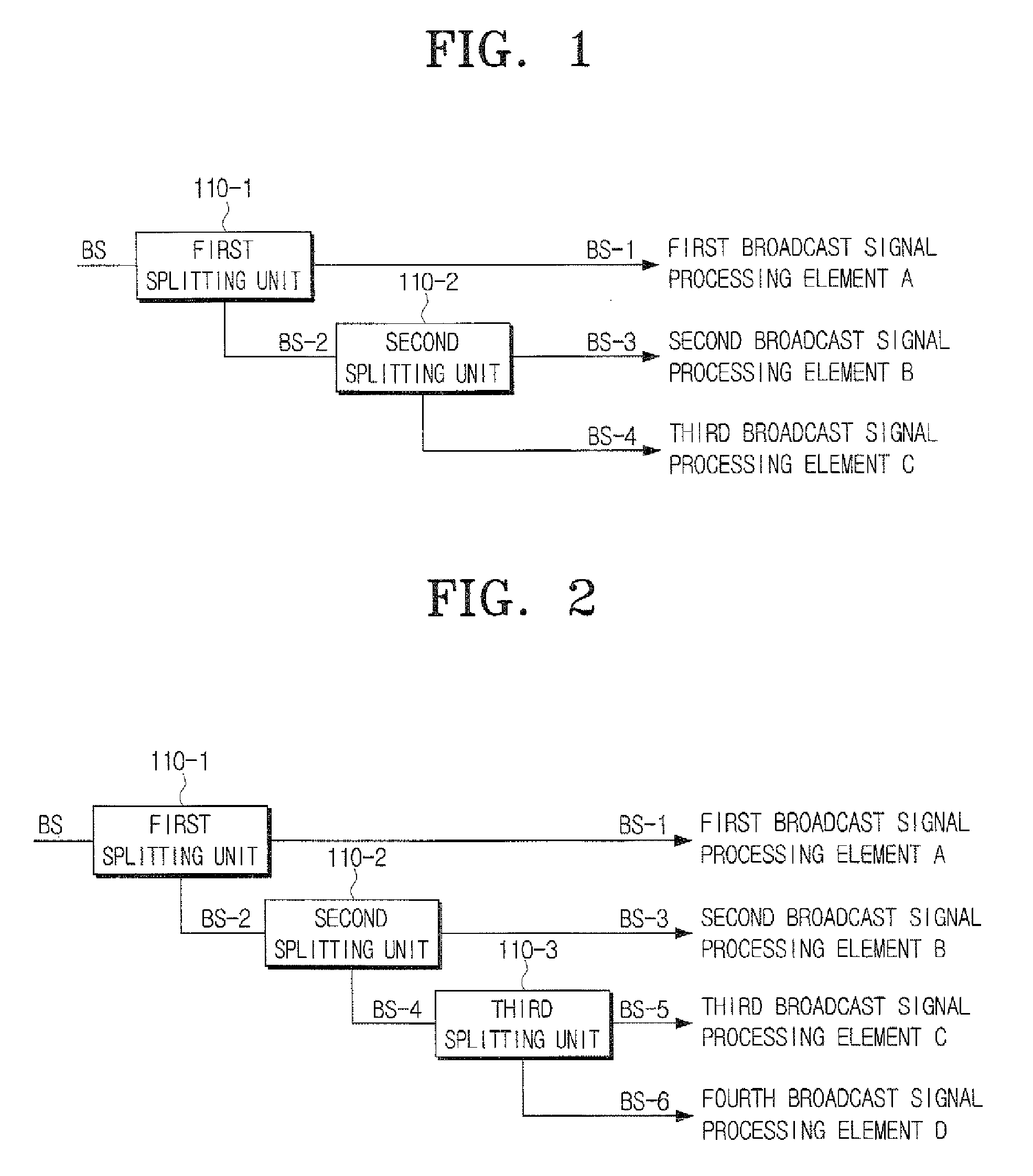
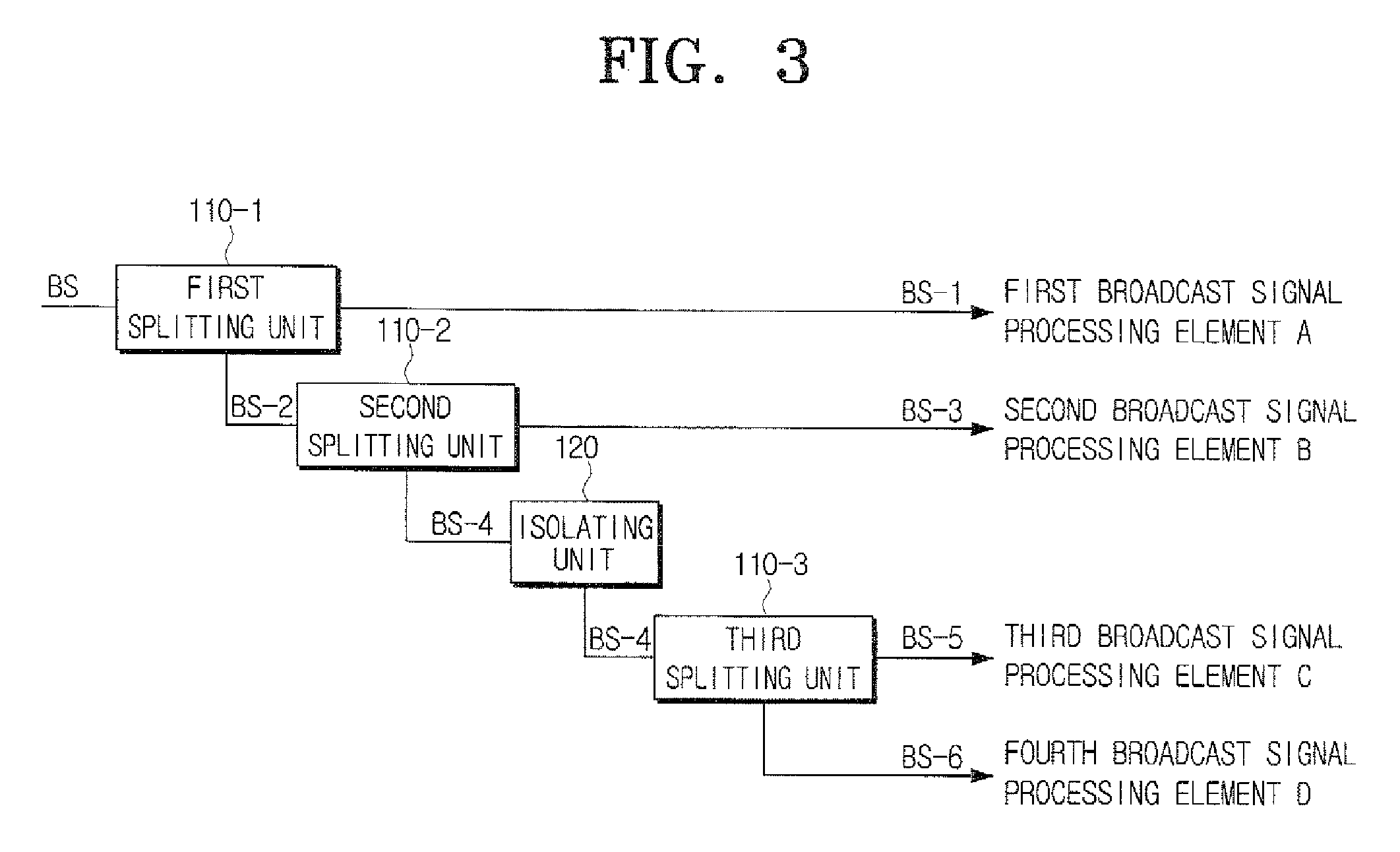
[0033]Hereinafter, an apparatus for splitting a signal in accordance with exemplary embodiments of the present invention and a video device using the same will be described in detail with reference to the accompanying drawing figures.

[0034]FIG. 1 is a block diagram exemplifying an apparatus for splitting a signal in accordance with a first exemplary embodiment of the present invention. As illustrated in FIG. 1, the signal splitting apparatus in accordance with the first exemplary embodiment of the present invention is provided with a first splitting unit 110-1 and a second splitting unit 110-2.

[0035]The first splitting unit 110-1 splits an inputted broadcast signal (referred as BS below) into a first broadcast signal (referred as BS-1 below) and a second broadcast signal (referred as BS-2 below). The BS inputted to the first splitting unit 110-1 may be a cable broadcast signal, which is received through a cable. The split BS-1 is split no longer, but supplied to a first broadcast pr...


PUM


Abstract

An apparatus for splitting a signal and a video device using the same are disclosed. The apparatus includes a first splitting unit to split an inputted broadcast signal into a first broadcast signal and a second broadcast signal, and to supply the first broadcast signal to a first broadcast signal processing element, and a second splitting unit to split the second broadcast signal into a third broadcast signal and a fourth broadcast signal, and to supply the third broadcast signal to a second broadcast signal processing element. With this construction, the apparatus can distribute and provide a broadcast signal with a noise figure (NF) lower than that of other broadcast signals, to an element, which requires a broadcast signal with a low noise figure. In addition, the apparatus can split the inputted broadcast signal without using an active element, such as an amplifier or the like, thereby allowing the split broadcast signals to lower the NF thereof and to uniformly maintain a gain thereof. Also, the apparatus can prevent interferences, which are generated between adjacent ports.

Description

CROSS-REFERENCE TO RELATED APPLICATIONS[0001]This application claims the benefit under 35 U.S.C. §119(a) of Korean Patent Application No. 10-2006-0110700, filed Nov. 9, 2006, in the Korean Intellectual Property Office, the entire disclosure of which is incorporated herein by reference.FIELD OF THE INVENTION[0002]The present invention relates generally to an apparatus for splitting a signal and a video device using the same. More particularly, the present invention relates to an apparatus for splitting a signal, which splits a single broadcast signal into a plurality of broadcast signals, and a video device using the same.BACKGROUND OF THE INVENTION[0003]To split a broadcast signal, various methods are known, but a method, which splits a single broadcast signal into two broadcast signals and then re-splits each of the split two broadcast signals into two broadcast signals to form four broadcast signals, is usually used.[0004]Since the four broadcast signals formed as described above ...

Claims


Application Information

Patent Timeline
Patent Type & Authority Patents(United States)
IPC IPC(8): H04N5/54
CPCH04N7/104H04H40/18H04H20/08H04N5/44
Inventor KWRK, BYUNG-JU
Owner SAMSUNG ELECTRONICS CO LTD
Why Eureka
Try Eureka