Eureka AIR delivers breakthrough ideas for toughest innovation challenges, trusted by R&D personnel around the world.

Position-dependent connectivity management

a connectivity management and position-dependent technology, applied in the field of position-dependent connectivity management, can solve the problems of cumbersome terminal user selection of the most effective wlan network, non-needing reception/transmission circuitry consumption of battery power for no useful purpose, etc., and achieve the effect of improving power management and streamlined entry

Active Publication Date: 2012-11-20
ELEKTROBIT WIRELESS COMM OY
View PDF10 Cites 25 Cited by
  • Summary
  • Abstract
  • Description
  • Claims
  • Application Information

AI Technical Summary

Benefits of technology

[0012]Benefits of the invention include a more streamlined entry into and exit from the various regions in which the different communication technologies are activated. By streamlining the entry into and exit from the various regions, the invention can also improve power management because the reception / transmission circuitry associated with each communication technology is activated only in locations in which that communication technology is available and useful. Without such automatic deactivation of the reception / transmission circuitry associated with inactive communication technologies, the terminal user should manually deactivate any non-needed reception / transmission circuitries. Any time the user forgets to perform such deactivation, the non-needed reception / transmission circuitries consume battery power for no useful purpose.

Problems solved by technology

The adaptability of such multimode terminals to varying communication environments causes certain problems, however.
One of the problems is caused by the fact that on entry to a new environment, the multimode terminal may try to attach to several different communication networks by the several alternative communication technologies.
Thus it is cumbersome for the terminal user to select the most effective WLAN network.
Any time the user forgets to perform such deactivation, the non-needed reception / transmission circuitries consume battery power for no useful purpose.

Method used


Image

  • Position-dependent connectivity management
  • Position-dependent connectivity management
  • Position-dependent connectivity management

Examples


Embodiment Construction

[0018]It was stated earlier that a multimode communication device according to the invention is capable of communicating in several communication modes, which may refer to alternative communication technologies and / or to different operating modes within a single communication technology. In order to keep the description of the specific embodiments reasonably compact, most of the following description relates to embodiments capable of changing the communication technology being used, because the such descriptions can be easily applied to changes of operating modes within a single communication technology.

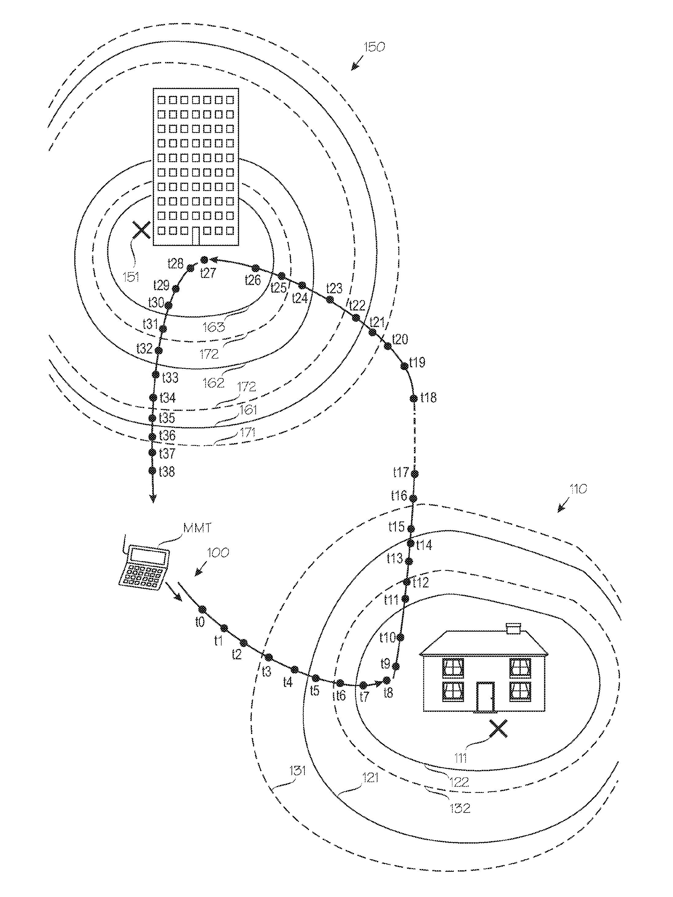
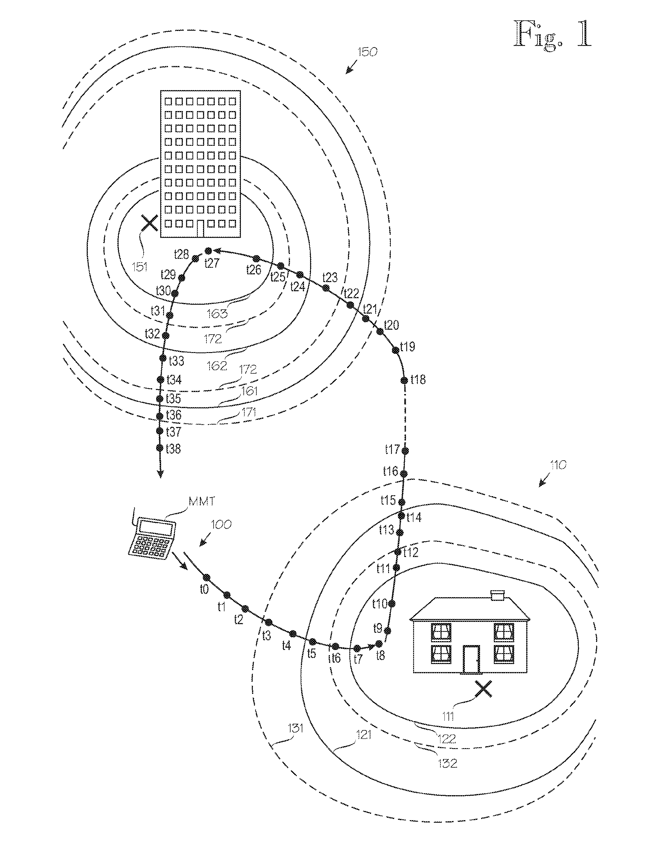
[0019]FIG. 1 illustrates an operating principle of the invention. Reference numeral 100 denotes a schematically drawn route of a multimode terminal. Reference signs t0 through t38 denote various instances of time, such that time instance tm occurs after time instance to if m>n. The multimode terminal is operable to use several (at least three) alternative communication technologies, ...


PUM


Abstract

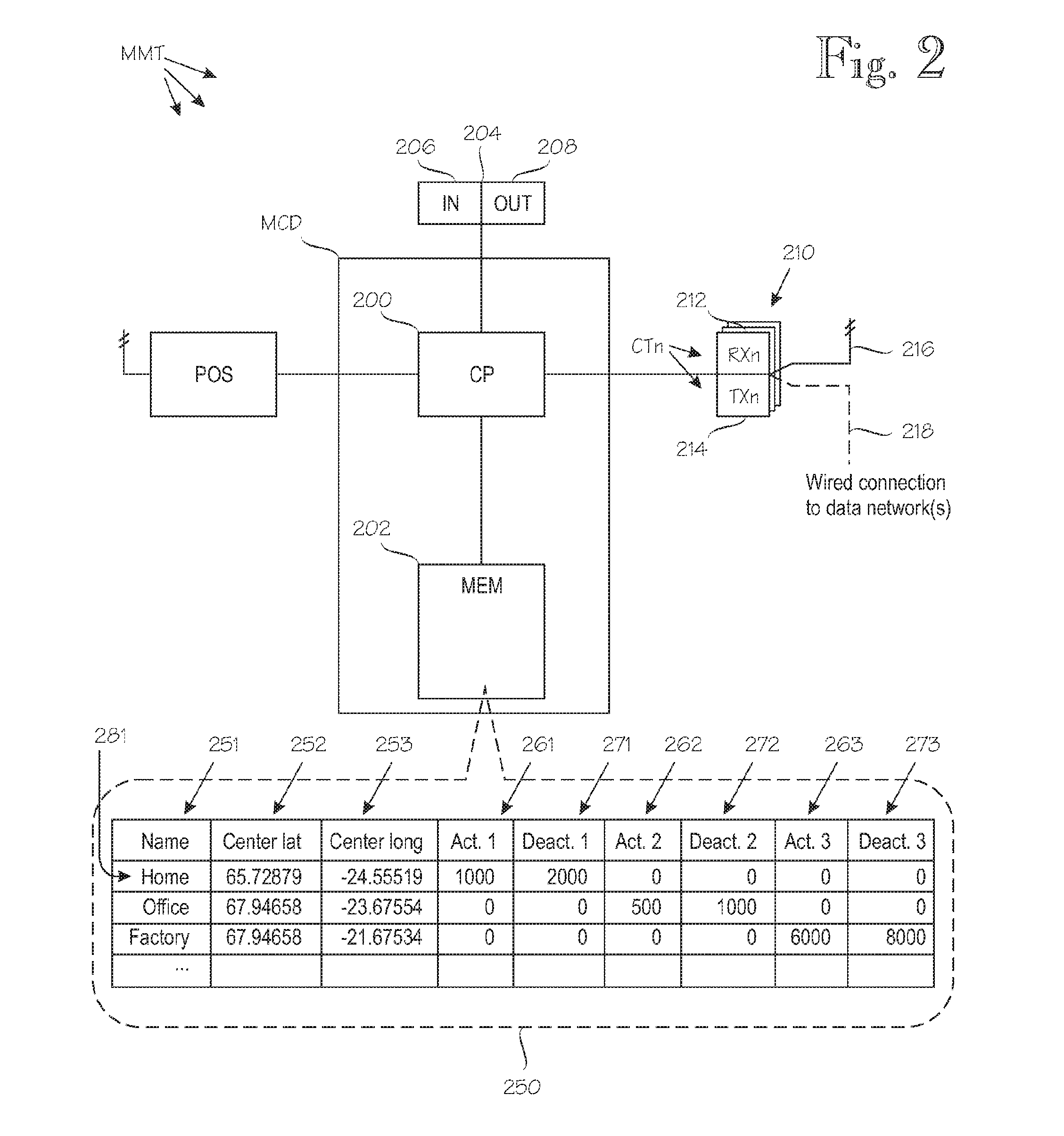
A method for communication to / from a multimode terminal operable to communicate via multiple alternative communication technologies. Each region definition indicates a region name and one or more of the communication technologies and / or operating modes plus an activation range and a deactivation range for the communication technologies and / or operating modes. The multimode terminal determines its position and retrieves a stored region definition relating to the region closest to the multimode terminal's determined position. It then compares its determined position with the activation range and a deactivation range of the retrieved region definition. Based on said comparison, the multimode terminal activates and deactivates the multiple alternative communication technologies and / or operating modes indicated by the retrieved region definition.

Description

CROSS-REFERENCE TO RELATED APPLICATIONS[0001]This application is a National Phase application of International Application No. PCT / FI2008 / 050476, filed on Aug. 28, 2008, which claims priority to Finnish Patent Application No. 20085604, filed on Jun. 18, 2008, which are incorporated herein by reference.BACKGROUND[0002]1. Field[0003]The invention relates to a position-dependent connectivity management and to a multimode communication device which may be a complete multimode communication terminal or a part of it.[0004]2. Brief Description of the Related Art[0005]In the context of the present disclosure, a multimode communication terminal means a communication terminal operable to communicate in several communication modes, wherein the several communication modes may refer to several alternative digital communication technologies and / or to different operating modes within a single communication technology. An illustrative but non-exhaustive list of such alternative communication techno...

Claims


Application Information

Patent Timeline
Patent Type & Authority Patents(United States)
IPC IPC(8): H04W24/00H04L67/14H04W4/02H04W4/021H04W4/029H04W4/50
CPCH04W4/001H04W4/02H04W4/021H04W48/16H04W48/04H04W48/18H04W64/00H04L67/12H04L67/18H04W4/50H04L67/52H04W4/029
Inventor KARJALAINEN, ANTTI
Owner ELEKTROBIT WIRELESS COMM OY
Why Eureka
Eureka Blog
Learn More