Bi-component drip emitter

a technology of drip emitter and component, which is applied in the field of drip emitters, can solve the problems of limiting the range of shapes that can be produced, increasing production costs, and requiring a relatively large proportion of elastomer materials

Active Publication Date: 2012-11-27
AMIRIM PRODS DEV & PATENTS
View PDF24 Cites 48 Cited by
  • Summary
  • Abstract
  • Description
  • Claims
  • Application Information

AI Technical Summary

Problems solved by technology

However, the use of a separate elastomer diaphragm dictates a two-part, or more often three-part, design, requiring an assembly step during production and thus increasing production costs.
The resulting structures have many advantages, but require a relatively large proportion of elastomer material, and are limited to the use of certain types of elastomer which provide sufficient structural support and which can be effectively bonded to the inner surface of an irrigation hose.
Furthermore, production by extrusion techniques inherently limits the range of shapes that can be produced, and provides relatively low manufacturing precision.
While promising significant advantages as mentioned, practical implementation of a bi-component drip emitter by bi-component molding presents various challenges.
Specifically, the device disclosed in my U.S. Pat. No. 5,203,503 typically fails to achieve reliable flow rate compensation due to the high sensitivity of the laminar flow restriction to variations in geometry (requiring ten times more precision than the turbulent variable geometry labyrinth options described below).
However, bi-component molding techniques are challenging to implement for devices which combine thermoset and thermoplastic components, and are particularly problematic for production of drip emitters due to the failure of silicone to bond firmly with adjacent rigid polymer material.

Method used


Image

  • Bi-component drip emitter
  • Bi-component drip emitter
  • Bi-component drip emitter

Examples


first embodiment

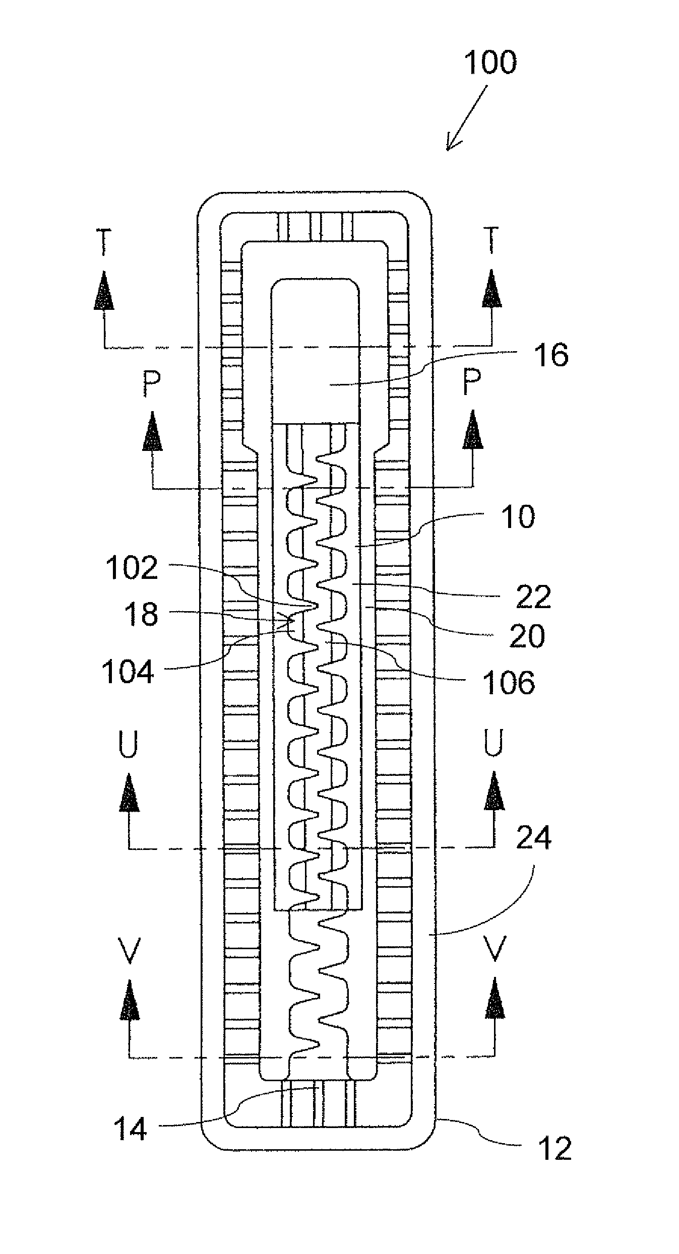
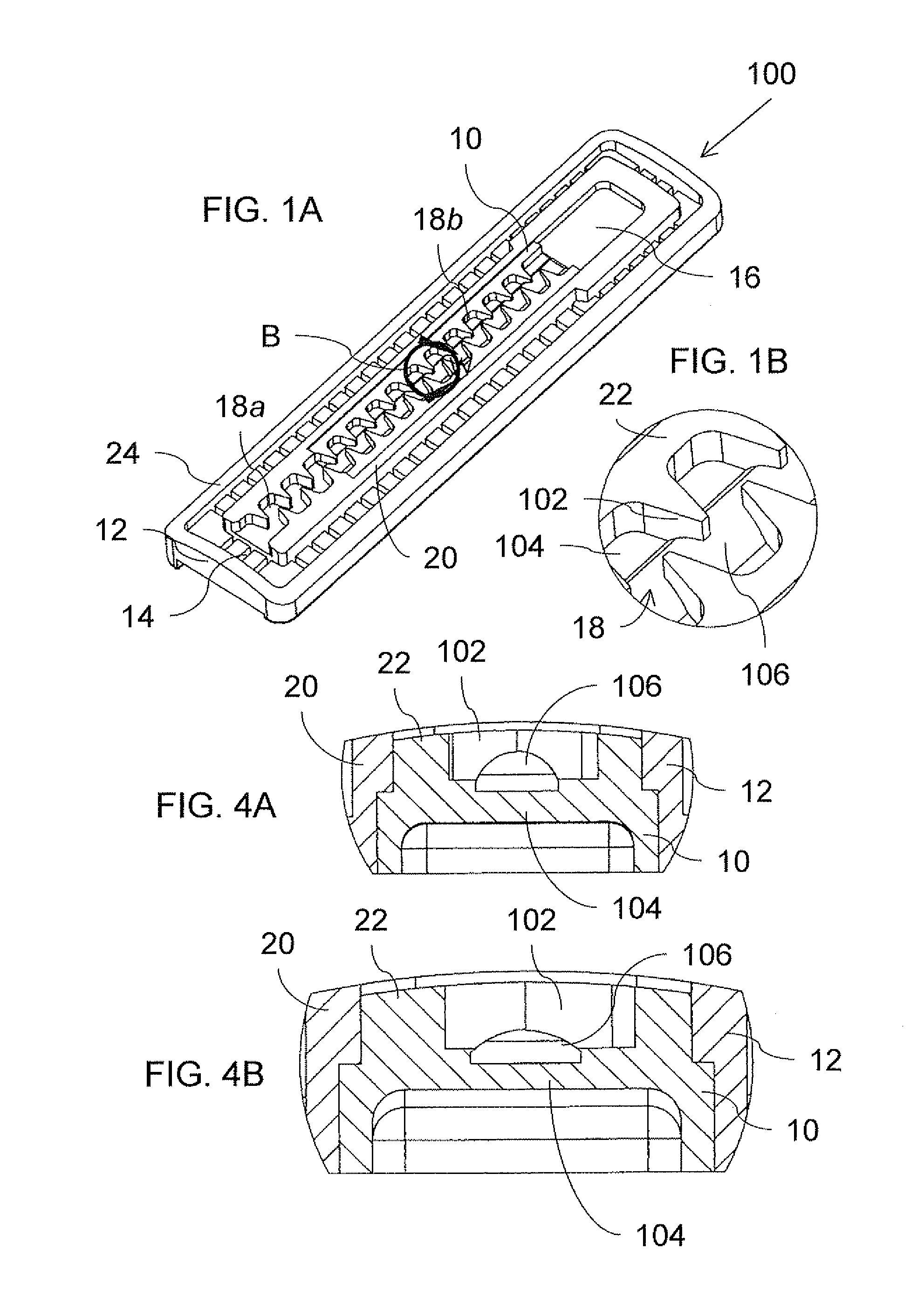
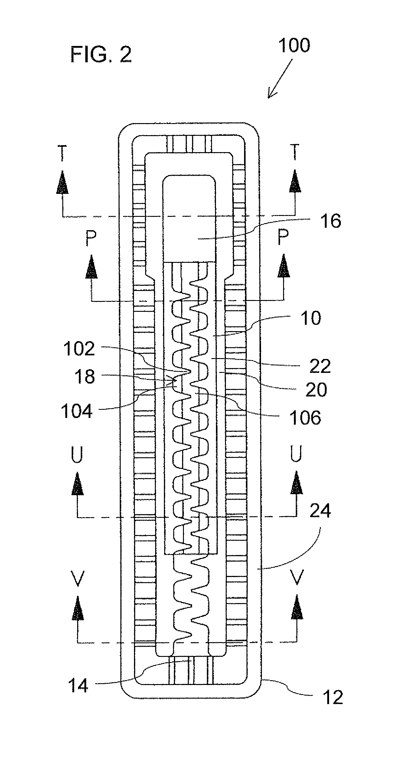
[0082]Referring now to the drawings, FIGS. 1A-5D show a drip emitter, generally designated 100, constructed and operative according to the present invention. Drip emitter 100 is of a type for attachment to an inner surface of a wall of an irrigation hose around less than half of the periphery of the irrigation hose at spaced apart locations along the irrigation hose, as will be illustrated specifically with reference to FIGS. 5A-5D.

[0083]As described in general terms above, drip emitter 100 includes an elastomer component 10 and a rigid polymer component 12, and is configured such that, when welded to the inner surface of the irrigation hose, drip emitter 100 defines a water inlet 14 for receiving water from the irrigation hose, a drip outlet 16 for releasing water through the wall of the irrigation hose, and a fluid flow pathway from the water inlet to the drip outlet. In the embodiment illustrated here, the fluid flow pathway is formed with a flow restriction implemented as a laby...

second embodiment

[0095]Referring now to FIGS. 6A-7C, these show a drip emitter, generally designated 200, constructed and operative according to the present invention. Generally speaking, drip emitter 200 is similar to drip emitter 100 described above, with equivalent elements being similarly labeled. Drip emitter 200 differs from drip emitter 100 primarily in that the under-tooth bypass spaces are here replaced by an over-tooth bypass clearances.

[0096]Thus, in the embodiment illustrated here, fluid flow pathway 18a, 18b is formed with a flow restriction implemented as a labyrinth formed by a sequence of baffles 202 and a base 204. At least part of the sequence of baffles 202 and base 204 corresponding to the variable geometry flow path 18b is integrally formed as part of the elastomer component 10.

[0097]Elastomer component 10 here also includes a series of bypass clearances 206 formed along the top edges of the sequence of baffles 202 such that, when welded to the inner surface of the irrigation ho...

third embodiment

[0101]Referring now to FIGS. 8A-8E, these show a drip emitter, generally designated 300, constructed and operative according to the present invention. Generally speaking, drip emitter 300 is similar to drip emitter 100 described above, with similar elements being similarly labeled. Drip emitter 300 differs from drip emitter 100 primarily in that it employs a labyrinth flow restriction with a variable cross-section flow geometry instead of the aforementioned under-tooth bypass spaces. This embodiment also illustrates an implementation in which both the fixed geometry labyrinth part of the flow path 18a and the variable geometry flow path 18b are integrally formed as part of the elastomer component 10.

[0102]Thus, in the embodiment illustrated here, fluid flow pathway 18a, 18b is formed with a flow restriction implemented as a labyrinth formed by a sequence of baffles 302 and a base 304. At least part of the sequence of baffles 302 and base 304, and in this case the entirety of the seq...


PUM

PropertyMeasurementUnit
pressureaaaaaaaaaa
lengthaaaaaaaaaa
flow rateaaaaaaaaaa

Abstract

A drip emitter formed from an elastomer component and a rigid polymer component for welding to the inner surface of an irrigation hose. The drip emitter has a fluid flow pathway including a flow restriction, typically in the form of a labyrinth, formed at least partially within the elastomer to provide a variable geometry flow restriction. The flow restriction may include under-tooth bypass spaces located between the base and the sequence of baffles, over-tooth bypass clearances or may employ baffles with a thickened root portion which forms a sloped transition region between an upright upper wall portion and the base. In each case, flow through the drip emitter when deployed is regulated by pressure-responsive deformation of the elastomer component. Some implementations employ a thermoset elastomer component such as silicone with mechanical interlocking between the components.

Description

FIELD AND BACKGROUND OF THE INVENTION[0001]The present invention relates to drip emitters for use with drip irrigation hose and, in particular, it concerns a bi-component drip emitter for attachment to an inner surface of a wall of an irrigation hose.[0002]Drip emitters for use in irrigation hoses include a flow restriction to reduce flow rates to the desired level. Examples of flow restrictions include, but are not limited to, laminar flow restrictions, and patterns of meandering fine flow passageways referred to as labyrinths.[0003]In some cases, elastomer materials are employed as part of a flow restriction designed to provide a variable flow restriction geometry. The variable geometry is designed to be responsive to the fluid pressure within the supply hose so as to at least partially compensate for flow rate variations due to changes in the pressure within the hose. An example of such an arrangement is my U.S. Pat. No. 5,400,973 in which a flat elastomer diaphragm is deformed b...

Claims


Application Information

Patent Timeline
Patent Type & Authority Patents(United States)
IPC IPC(8): B05B15/00
CPCA01G25/023Y10T29/494Y02A40/22
Inventor COHEN
Owner AMIRIM PRODS DEV & PATENTS
Why Eureka
Try Eureka