Charging connector

a charging connector and connector technology, applied in the direction of charging stations, transportation and packaging, coupling device connections, etc., can solve the problems of affecting affecting the operation colliding with the ground, so as to improve the design appearance of the charging connector, facilitate the operation of unlocking, and improve the effect of the charging connector's design appearan

Inactive Publication Date: 2012-11-27
SUMITOMO WIRING SYST LTD
View PDF8 Cites 30 Cited by
  • Summary
  • Abstract
  • Description
  • Claims
  • Application Information

AI Technical Summary

Benefits of technology

[0008]The lock release accommodating portion may include a front wall arranged to face a front surface of the pressable portion. The front wall may be connected to front ends of the side walls of the lock release accommodating portion. According to this construction, the lock release is protected by the front wall of the lock release accommodating portion when the charging connector is dropped by mistake. Further, the front ends of the side walls of the lock release accommodating portion are connected by the front wall to strengthen the entire lock release accommodating portion.
[0011]The lock release accommodating portion may be an inner peripheral wall of a hole formed in an outer surface of the case and the lock release may face the back side of the case through the hole. According to this construction, the outer contour line of the case can be smooth to improve the design appearance of the charging connector.
[0012]The case may include a main body extending in a connecting direction with the vehicle-side connector and a grip extending from a rear end of the main body in a direction crossing the connecting direction. The unlocking portion may be near a boundary between the main body and the grip. According to this construction, the pressable portion of the unlocking portion is more easily pressed by a thumb when the grip is held by hand.

Problems solved by technology

The unlocking portion is exposed to a lateral side in the above-described charging connector and can collide with the ground, for example, if the charging connector is dropped accidently.
Thus, the unlocking portion is subject to an impact and can break.

Method used


Image

  • Charging connector
  • Charging connector
  • Charging connector

Examples


Embodiment Construction

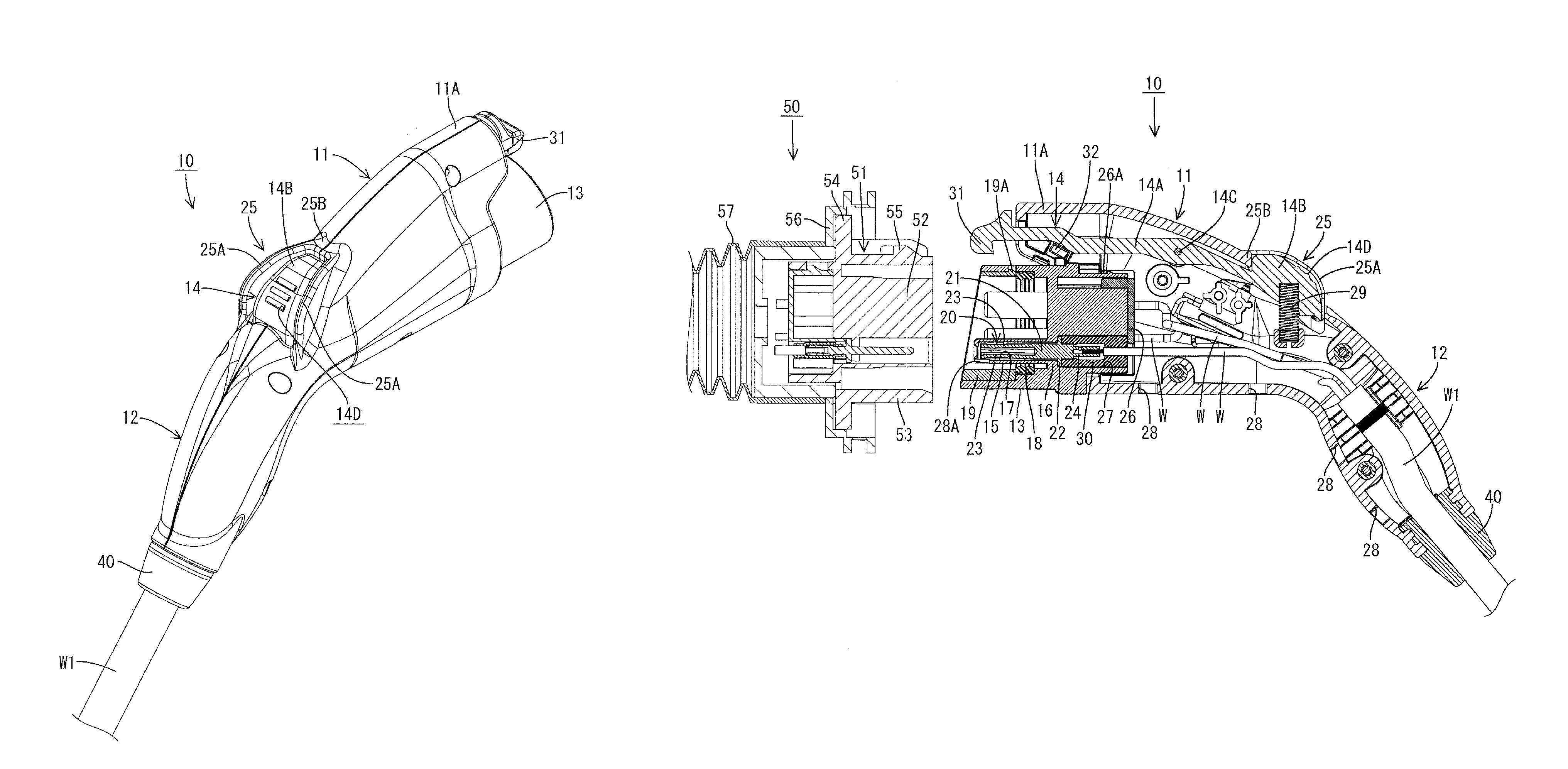
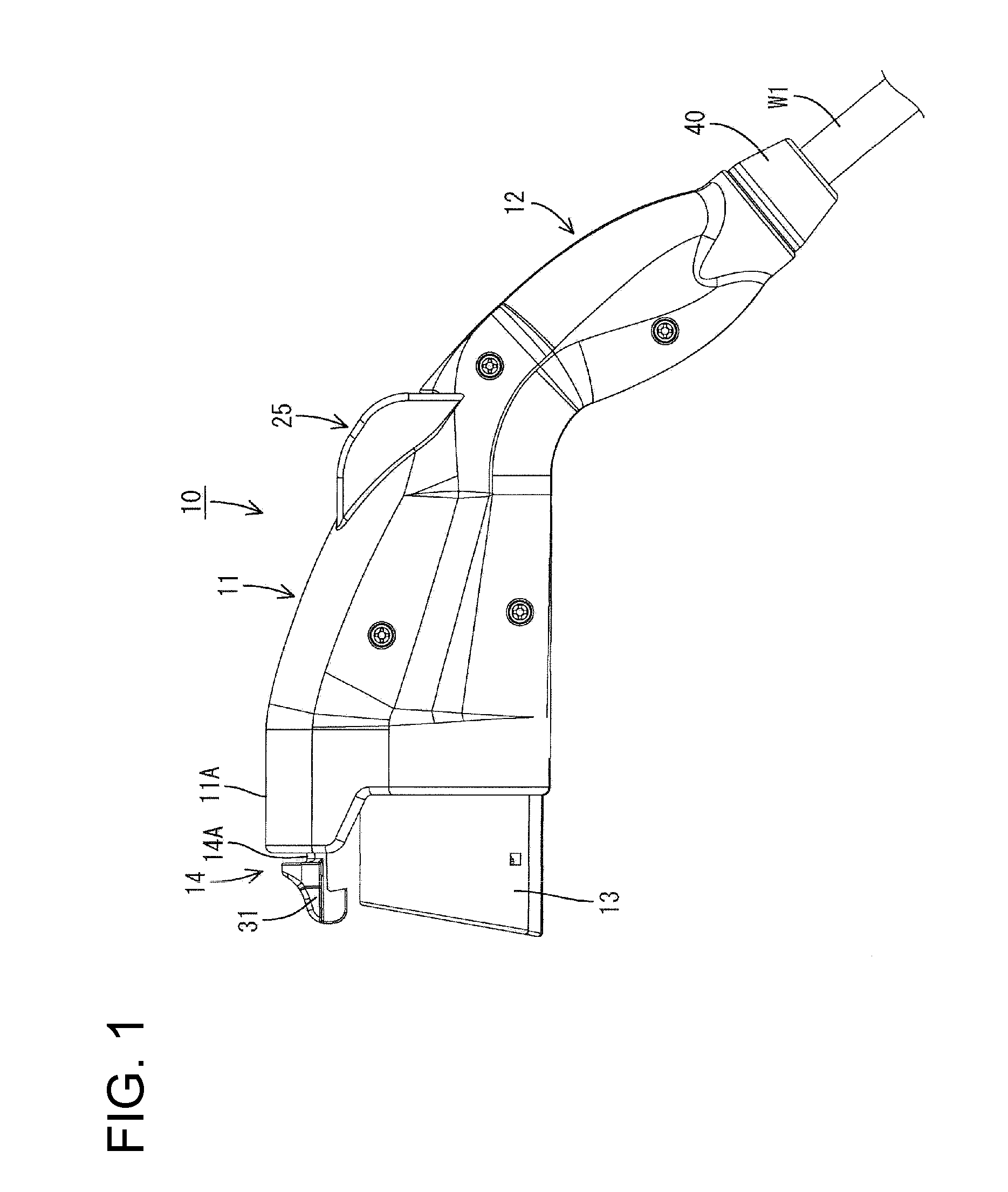
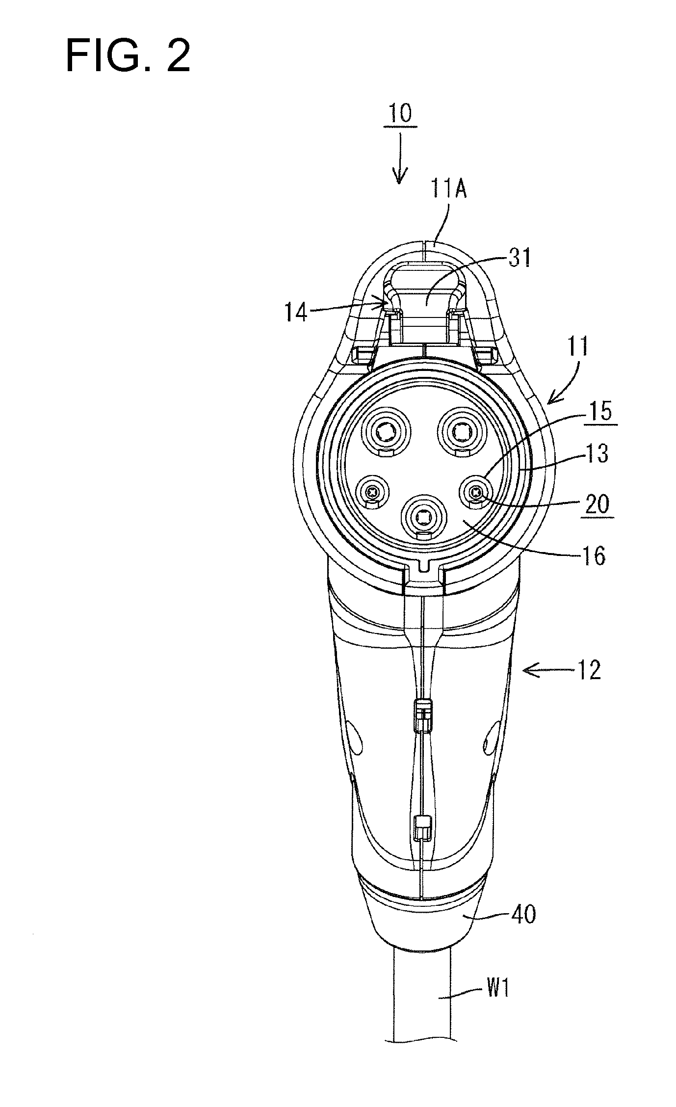
[0027]A first embodiment of the invention is described with reference to FIGS. 1 to 8. The charging connector 10 is connectable with a vehicle-side connector 50. A connection direction of the charging connector 10 with the vehicle-side connector 50 is referred to herein as the forward direction and hence defines the front end of the charging connector 10. The charging connector 10 is substantially gun-shaped and has a main body 11 at a front part and a grip 12 extending obliquely down from a rear part of the main body 11, as shown in FIG. 1. The main body 11 and the grip 12 are made e.g. of synthetic resin and may be molded unitarily. A tubular fitting 13 projects forward at the front of the main body 11. Further, a lever 14 is accommodated at an upper side of the interior of the main body 11 so that a front end of the lever 14 projects forward from the front edge of the upper surface of the main body 11 to be exposed to the outside. Note that the main body 11 may be considered a ca...


PUM


Abstract

A charging connector (10) is provided to be connected to a vehicle-side connector (50) to charge a battery. The charging connector (10) has a main body (11) including a fitting (13) connectable to the vehicle-side connector (50), a lever (14) accommodated in the main body (11) and adapted to hold the vehicle-side connector (50) and the fitting (13) in a connected state by being engaged with a lock projection (55) provided on the vehicle-side connector (50). A lock release (14B) is provided in the lever (14) and for canceling a locked state of a lock (31) and the lock projection (55), and a lock release accommodating portion (25) is formed at a position of the main body (11) corresponding to the lock release (14B) and includes two sidewalls (25A) arranged to face opposite side surfaces of a pressable portion (14D) to be pressed at the time of an unlocking operation.

Description

BACKGROUND OF THE INVENTION[0001]1. Field of the Invention[0002]The invention relates to a charging connector connectable to a vehicle-side connector for charging a battery in a vehicle.[0003]2. Description of the Related Art[0004]U.S. Pat. No. 5,820,395 discloses a charging connector that is connectable to a vehicle-side connector for charging a battery in a vehicle. This connector includes a fitting that is mounted in a front end opening of a case and that is connectable to a vehicle-side connector. The charging connector also has a lever extending forward from the interior of the case. The charging connector and the vehicle-side connector are held in a connected state by the engagement of a lock at a front end of the lever with a lockable portion on the vehicle-side connector. Further, an unlocking portion is provided at a rear end of the lever and is capable of canceling a locked state of the lock and the lockable portion.[0005]The unlocking portion is exposed to a lateral side ...

Claims


Application Information

Patent Timeline
Patent Type & Authority Patents(United States)
IPC IPC(8): H01R13/627
CPCB60L11/1818H01R13/6275B60L2270/34Y02T90/14B60L2270/32Y02T10/7005Y02T10/7072B60L53/16Y02T10/70H01R13/5227
Inventor OSAWA, KIYOSHIICHIO, TOSHIFUMI
Owner SUMITOMO WIRING SYST LTD
Why Eureka
Try Eureka