Check patentability & draft patents in minutes with Patsnap Eureka AI!

Locking device and electronic enclosure using the same

a technology of electronic enclosure and locking device, which is applied in the direction of coupling device connection, electrical apparatus casing/cabinet/drawer, instruments, etc., can solve the problems of time-consuming and troublesom

Inactive Publication Date: 2012-11-27
HONG FU JIN PRECISION IND (SHENZHEN) CO LTD +1
View PDF6 Cites 11 Cited by
  • Summary
  • Abstract
  • Description
  • Claims
  • Application Information

AI Technical Summary

Benefits of technology

[0005]Conventionally, a number of screws are applied to lock the cover to the base. However, such methods need additional tools such as screwdrivers to be used during the assembly, which is time consuming and troublesome.

Problems solved by technology

However, such methods need additional tools such as screwdrivers to be used during the assembly, which is time consuming and troublesome.

Method used


Image

  • Locking device and electronic enclosure using the same
  • Locking device and electronic enclosure using the same
  • Locking device and electronic enclosure using the same

Examples


Embodiment Construction

[0021]The locking device for an electronic enclosure in accordance with an exemplary embodiment of the present disclosure is applied to a monitor as an example. Understandably, the locking device can be used in computer housings or other electronic devices.

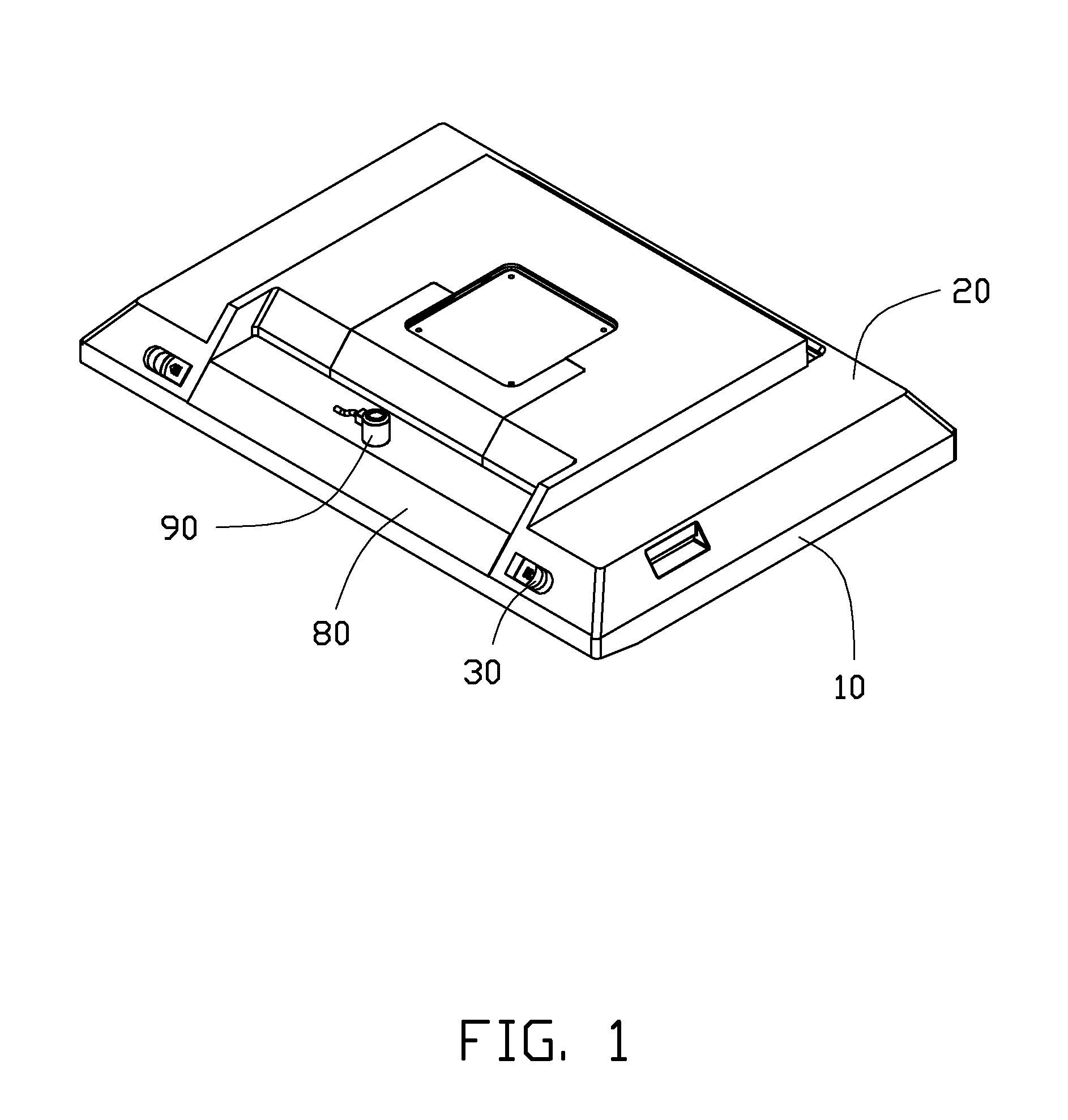
[0022]Referring to FIGS. 1-4, the electronic enclosure includes a base 10, a cover 20, a back plate 80, and a locking device. The locking device includes a first locking module 30 assembled on the cover 20, and a second locking module 90 assembled on the base 10. The second locking module 90 is used to lock to the first locking module 30 and fasten the back plate 80 on the base 10. In other embodiments, the back plate 80 and the cover 20 can be integrally made.

[0023]Referring to FIGS. 5-7, the base 10 includes a baffle 11 extending upwards from a front end of the base 10. The baffle 11 is lengthwise and defines a supporting plate 15 extending backwards from a top edge of the baffle 11. The supporting plate 15 defines a slot 150 at...


PUM


Abstract

An electronic enclosure includes a base, a cover mounted on the base, a first locking module engaged on the cover, a second locking module, and a locking structure. The base defines a number of supporting recesses defined therein. The cover includes a number of barbs for matching with the supporting recesses of the base. The second locking module includes at least one locking member. The at least one locking member includes a pivot portion pivotably engaging with the base, a first end and a second end opposite to the first end. The locking structure abuts the first end of the at least one locking member to rotate the second end to engage with the first locking module, whereby the cover is fixed on the base.

Description

BACKGROUND[0001]1. Technical Field[0002]The present disclosure relates to locking devices, and particularly to a locking device for an electronic enclosure.[0003]2. Description of Related Art[0004]An enclosure of an electronic device such as a computer housing or a monitor, includes a base and a cover covering the base. Electronic elements such as a main board can be assembled to the base and then the cover is applied to seal the enclosure, protecting the electronic elements.[0005]Conventionally, a number of screws are applied to lock the cover to the base. However, such methods need additional tools such as screwdrivers to be used during the assembly, which is time consuming and troublesome.[0006]Therefore, there is room for improvement within the art.BRIEF DESCRIPTION OF THE DRAWINGS[0007]FIG. 1 is an isometric view of a locking device in accordance with an exemplary embodiment of the disclosure applied to a monitor.[0008]FIG. 2 is an exploded, isometric view of the locking device...

Claims


Application Information

Patent Timeline
Patent Type & Authority Patents(United States)
IPC IPC(8): H05K5/00E05C3/12
CPCH05K5/0221Y10T292/1043Y10T292/1044
Inventor XU, CHANG-ZHENGLIN, YANG-MINGCHEN, HSUAN-TSUNGLEE, GUANG-YAO
Owner HONG FU JIN PRECISION IND (SHENZHEN) CO LTD
Features
  • R&D
  • Intellectual Property
  • Life Sciences
  • Materials
  • Tech Scout
  • Unparalleled Data Quality
  • Higher Quality Content
  • 60% Fewer Hallucinations
Learn More