Lens module

a technology of lenses and modules, applied in the field of lenses, can solve the problems of low precision and affect the quality of the image, and achieve the effect of improving the quality and the accuracy

Inactive Publication Date: 2012-11-27
HON HAI PRECISION IND CO LTD
View PDF1 Cites 16 Cited by
  • Summary
  • Abstract
  • Description
  • Claims
  • Application Information

AI Technical Summary

Benefits of technology

[0004]Opaque plates are used in lens modules for blocking off-axis light rays from entering the lens modules. Such an opaque plate is typically a thin, annular plate and can be assembled to the lens module via being held by a lens barrel of the lens module and sandwiched by two adjacent lenses of the lens module. However, it is precision work to make the opaque plate fit with the lenses efficiently. Often the precision is low and the quality is affected.

Problems solved by technology

Often the precision is low and the quality is affected.

Method used


Image

  • Lens module
  • Lens module
  • Lens module

Examples


Embodiment Construction

[0009]Embodiments of the present lens module will now be described in detail below and with reference to the drawings.

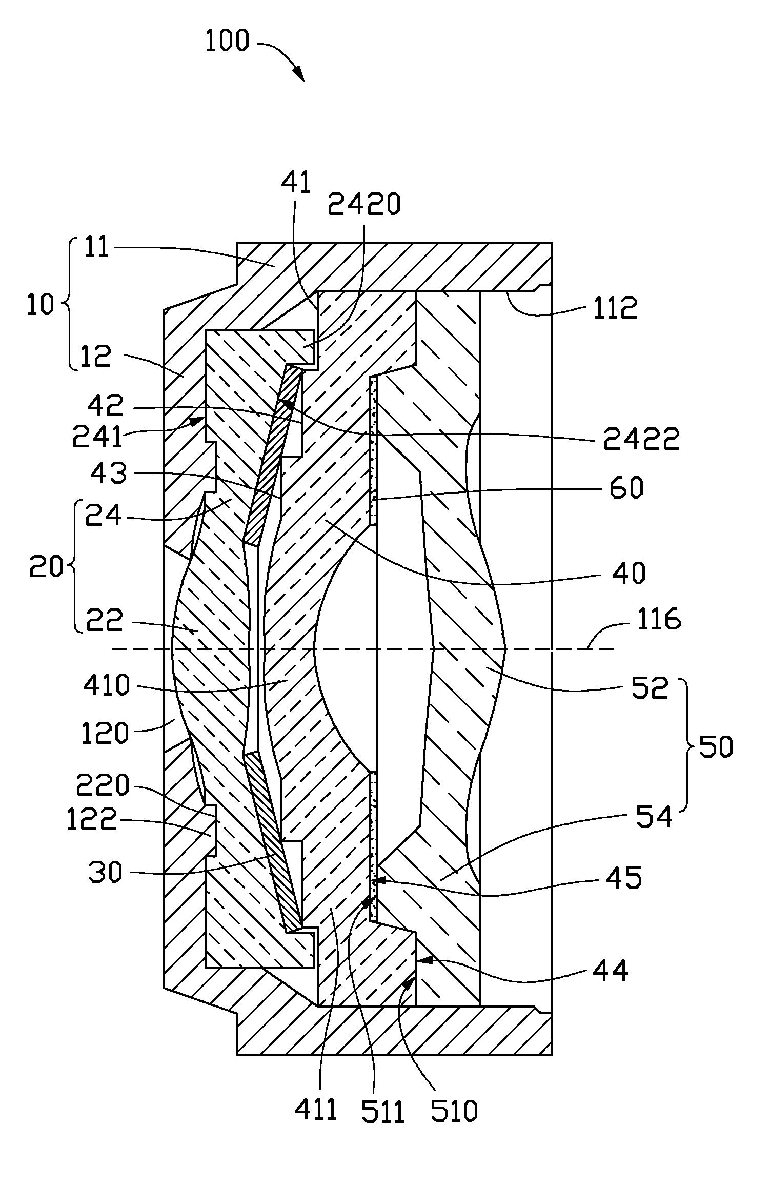
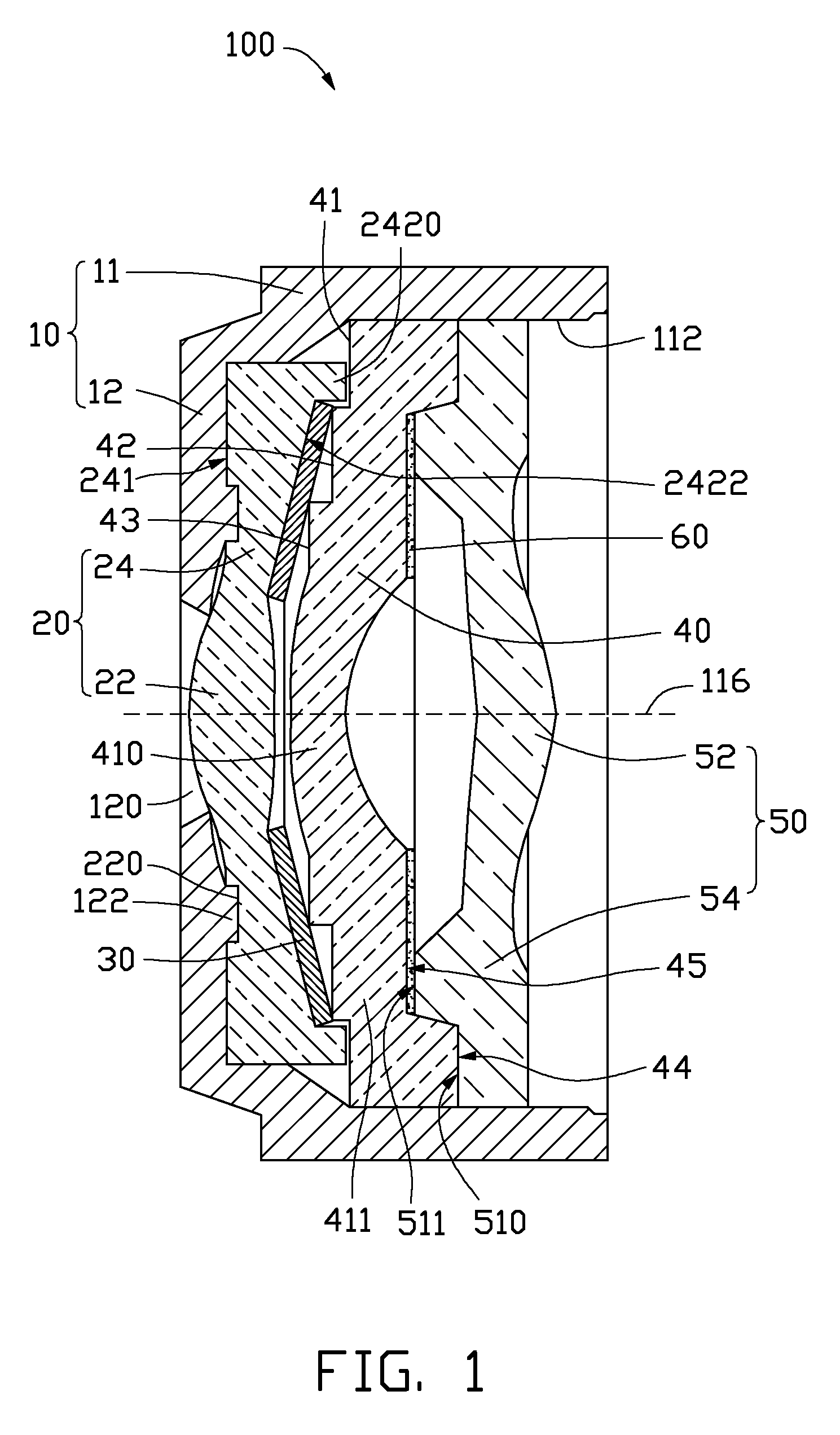
[0010]Referring to FIG. 1, a lens module 100, according to an exemplary embodiment, includes a lens barrel 10, a first lens 20, an annular conic opaque plate 30, a second lens 40, and a third lens 50. The first lens 20, the opaque plate 30, the second lens 40, and the third lens 50 are substantially coaxially received in the lens barrel 10 in the order from the object-side to the image-side of the lens module 100. The lens module 100 defines an imaging axis 116.

[0011]The lens barrel 10 is a hollow cylinder in shape and includes a main body 11 and an annular aperture plate 12. The annular aperture plate 12 is positioned at the object-side end of the main body 11 and is integrally formed with the main body 11. The annular aperture plate 12 defines an aperture opening 120 generally at the center thereof to allow light rays from objects of interest (not shown) to enter t...


PUM


Abstract

A lens module includes a lens barrel, a first lens, an opaque plate, and a second lens. The first lens includes an imaging portion and a non-imaging portion surrounding the imaging portion. The non-imaging portion defines an annular conic surface. The opaque plate is annular conic shaped and contacts with the annular conic surface. The second lens includes an imaging portion and a non-imaging portion surrounding the imaging portion. The object-side surface of the non-imaging portion of the second lens is step-like shaped and includes at least two step surfaces. A junction of two adjacent step surfaces abuts against the opaque plate.

Description

BACKGROUND[0001]1. Technical Field[0002]The present disclosure relates to a lens module.[0003]2. Description of Related Art[0004]Opaque plates are used in lens modules for blocking off-axis light rays from entering the lens modules. Such an opaque plate is typically a thin, annular plate and can be assembled to the lens module via being held by a lens barrel of the lens module and sandwiched by two adjacent lenses of the lens module. However, it is precision work to make the opaque plate fit with the lenses efficiently. Often the precision is low and the quality is affected.[0005]Therefore, it is desirable to provide a lens module which can overcome the above-mentioned problems.BRIEF DESCRIPTION OF THE DRAWING[0006]Many aspects of the present lens module can be better understood with reference to the accompanying drawings. The components in the drawings are not necessarily drawn to scale, the emphasis instead being placed upon clearly illustrating the principles of the present lens ...

Claims


Application Information

Patent Timeline
Patent Type & Authority Patents(United States)
IPC IPC(8): G02B9/00G02B7/02G02B9/04
CPCG02B5/003G02B5/005G02B7/022G02B27/0988H04N5/2254
Inventor LIN, TSUNG-YU
Owner HON HAI PRECISION IND CO LTD
Why Eureka
Try Eureka