

High-precision two-part flat chuck device and processing apparatus installed there-with
- Summary
- Abstract
- Description
- Claims
- Application Information
AI Technical Summary
Benefits of technology
Problems solved by technology
Method used
Image

Examples
Embodiment Construction
[0025]Embodiments of the present invention are further described in detail n combination with drawings now. The drawings are simplified schematic diagrams, only illustrate a basic structure of the present invention in a schematic way, and thus, only show a composition related to the present invention.
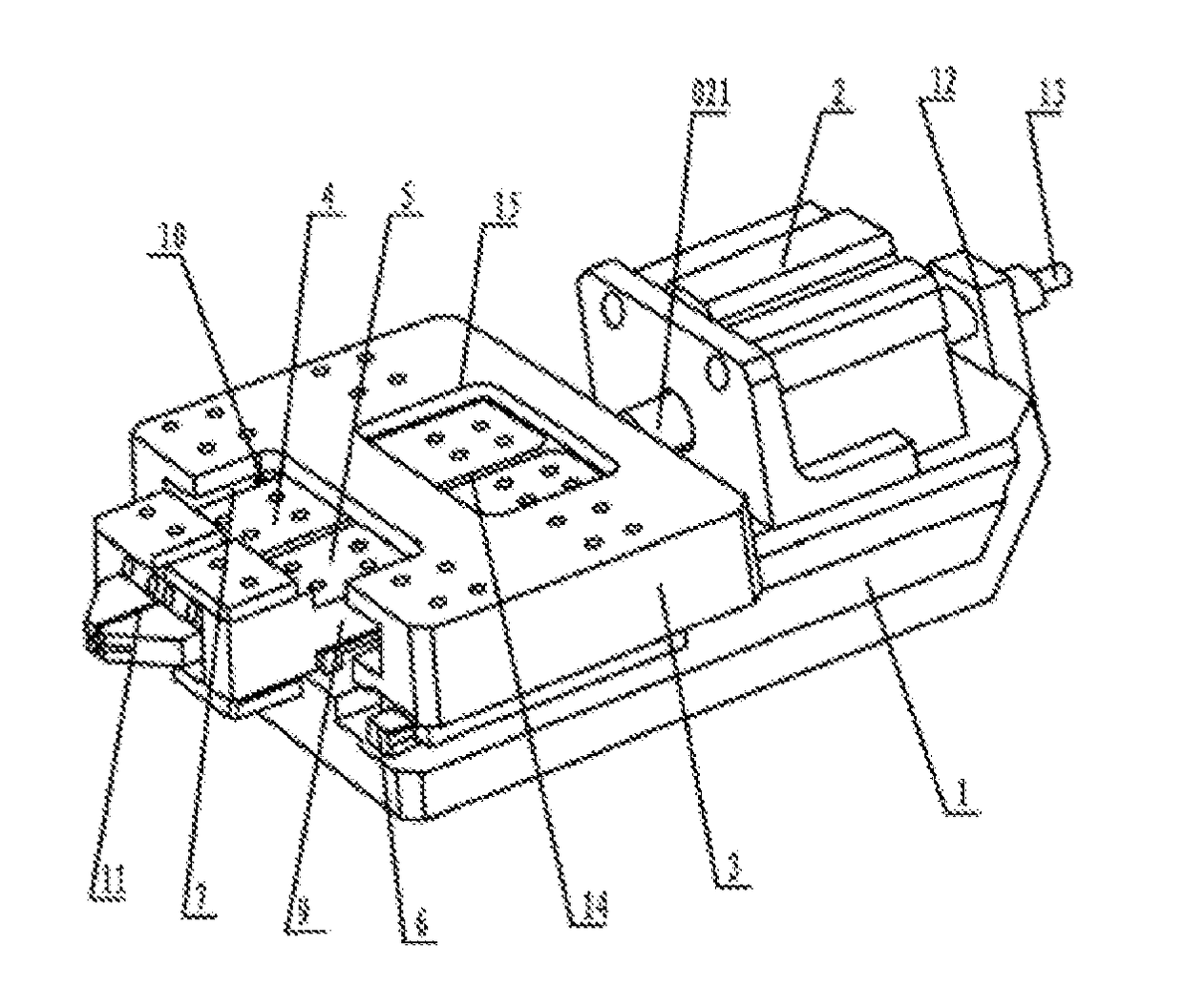
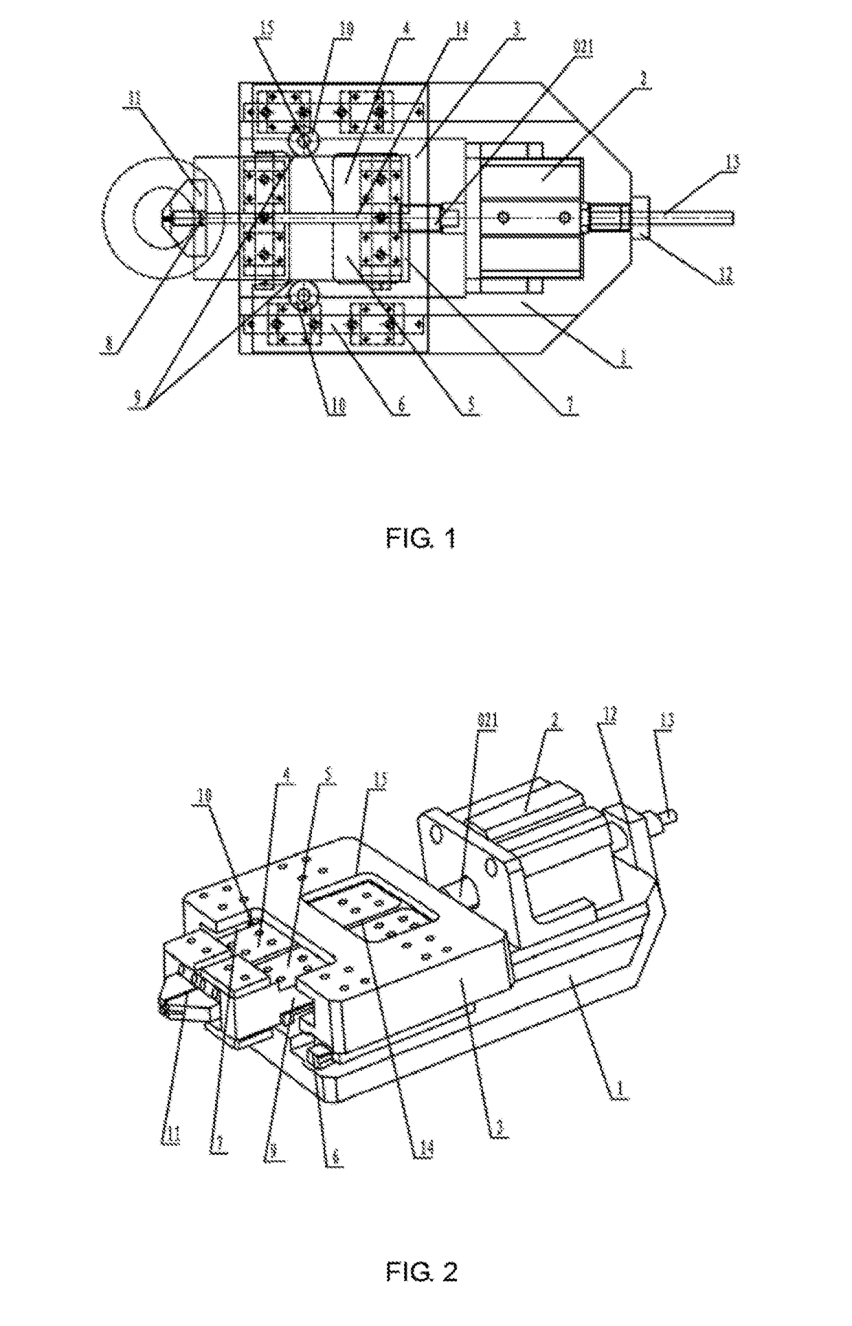
[0026]As shown in the figure, a high-precision two-part flat chuck device 19 comprises a base 1, a cylinder 2, a sliding plate 3, a first clamping plate 4 and a second clamping pate 5. A piston rod 021 of the cylinder 2 is connected with the sliding plate 3. Precision sliding rails 6 are arranged at two sides of the base 1 and two sides of the sliding plate 3 are respectively matched with the precision sliding rails 6 in a sliding manner. An accommodating groove 7 is arranged in a middle part of the sliding plate 3. The first clamping plate 4 and the second damping plate 5 are symmetrically distributed in the accommodating groove 7 along a center of the sliding plate 3, and a spring 8 i...
PUM
 Abstract
Description
Claims
Application Information