
Heliostat calibration and control

a technology of heliostats and calibration methods, applied in the field of solar energy collection apparatuses, can solve the problems of inability to address the calibration of inexpensive and inaccurate heliostats, and the magnitude of misalignment is relatively large before corrective action, so as to improve the accuracy of its receipt

Inactive Publication Date: 2013-10-31
COMMONWEALTH SCI & IND RES ORG
View PDF14 Cites 15 Cited by
  • Summary
  • Abstract
  • Description
  • Claims
  • Application Information

AI Technical Summary

Benefits of technology

The present invention introduces a new design and operation method for heliostats by substituting high precision encoders with low precision encoders and a continuous closed loop control system. This provides a cost-effective solution while still ensuring optimal performance by continuously and systematically re-aligning heliostats for optimal sunlight reception. The closed loop control system also compensates for heliostat and actuator geometry tolerances and improves accuracy in receiving the diverted beam of sunlight. The combination of open loop and closed loop positioning results in highly accurate tracking, allowing compensation for the tolerances in heliostat and actuator geometries.

Problems solved by technology

A challenge with central receiver solar energy collection systems is the trade off, in relation to the heliostats, between manufacturing cost and manufactured accuracy.
A problem with this technique is that it does not address the calibration of inexpensive and inaccurate heliostats.
A problem with this technique is that the magnitude of the misalignment is relatively large before corrective action is required.
As a result the heliostat field would be susceptible to operate for extended periods at suboptimal heliostat alignment and hence sub optimal heliostat field performance.

Method used


Image

  • Heliostat calibration and control
  • Heliostat calibration and control
  • Heliostat calibration and control

Examples


Embodiment Construction

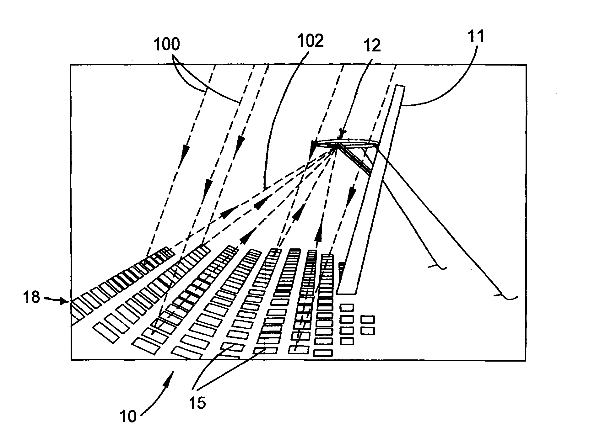
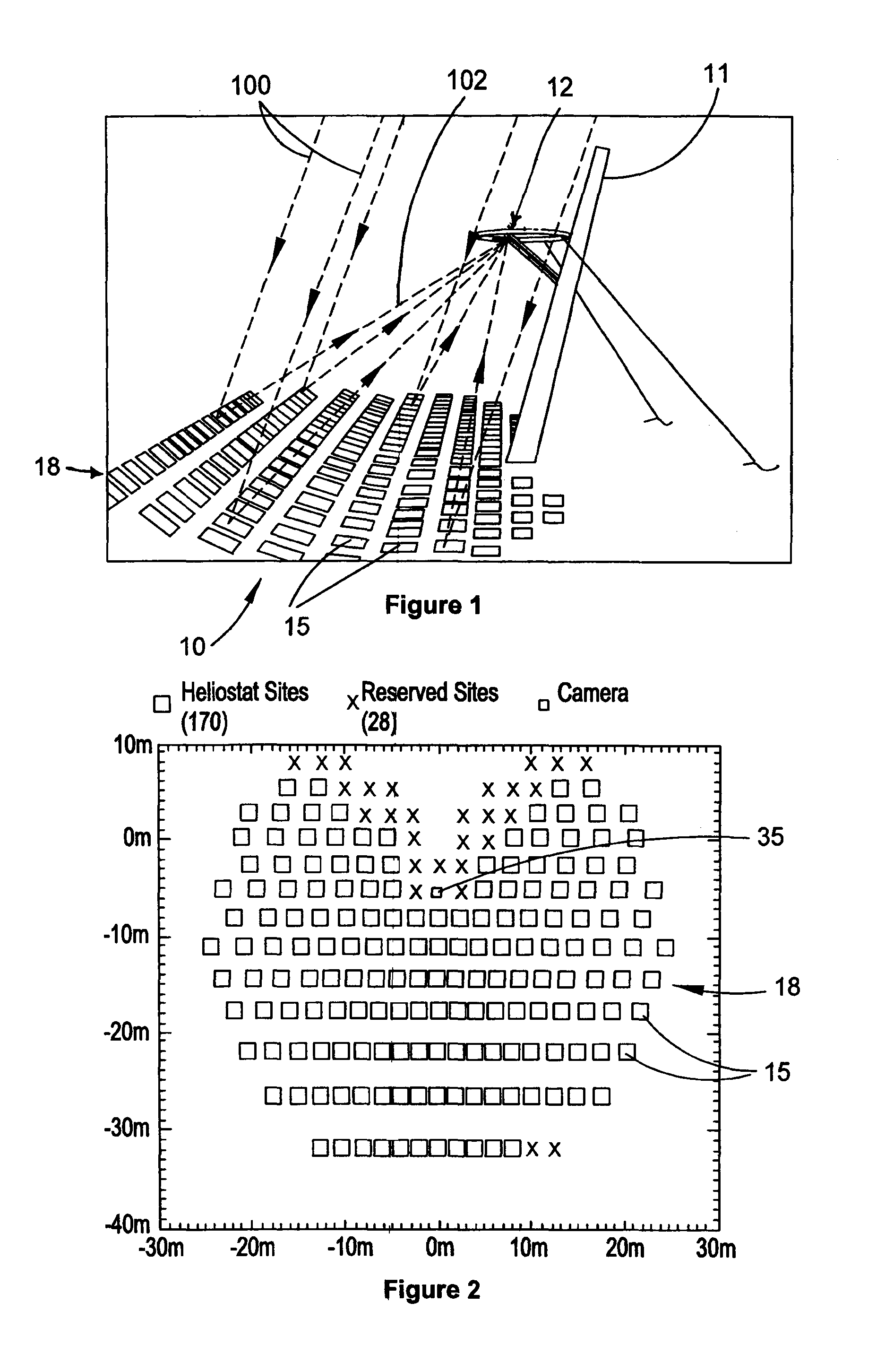
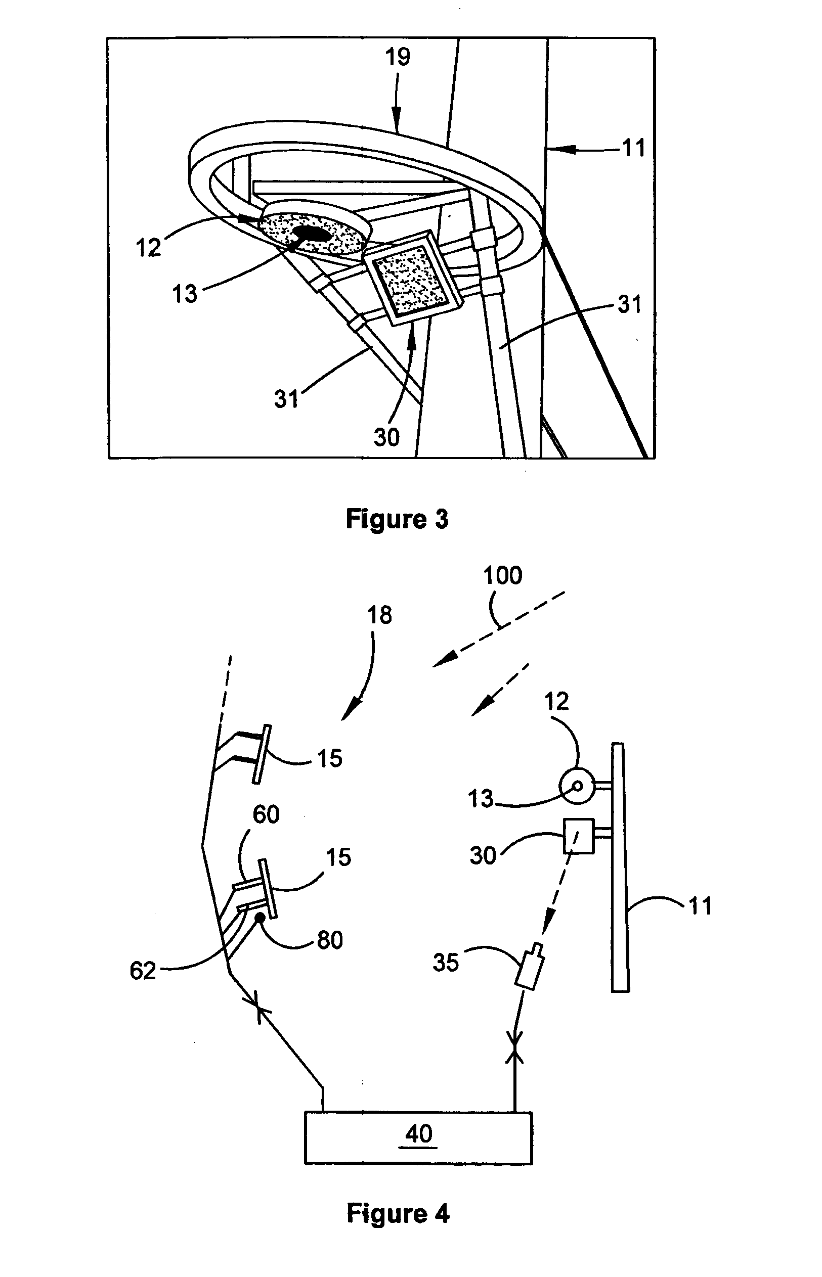
[0070]The present invention has particular utility in the operation of a central receiver solar energy collection system utilising inexpensively manufactured heliostats. Such a system 10 is depicted in FIGS. 1 and 2. The system comprises a central solar energy receiver 12 mounted in cantilevered fashion from a tower 11 above and in front of a large array or field 18 of heliostats 15. Heliostats 15 are mounted for angular adjustment to optimally receive a respective beam of sunlight 100 and to direct the beam, as a directed beam 102, to the solar receiver 12. Receiver 12 has an aperture 13 (FIG. 3) that defines a primary target to receive the directed beams of sunlight from the heliostats.

[0071]An optimally receiving position in this context is the angular position of the heliostat determined by a central controller, discussed further below, to be the appropriate position at the particular time on the particular date at which the respective heliostat makes a desired contribution to t...


PUM


Abstract

A solar energy collector including a solar energy receiver defining a primary target; and a field of heliostats mounted for angular adjustment to receive and direct sunlight to the primary target and an actuator to effect the angular adjustment of each heliostat. A secondary target at or spaced from the primary target. A controller coupled to the actuator configured to sequentially cause, a temporary angular adjustment of the respective the heliostats so as to divert the beam of sunlight received at each heliostat to the secondary target for a predetermined period of time. A recorder to record a representation of each diverted beam at the secondary target. The controller is coupled to the recorder and further configured to respond to the representation of the diverted beam for the respective heliostats when a parameter deviates from norm, by activating the actuator to angularly adjust the corresponding heliostat.

Description

FIELD OF THE INVENTION[0001]This invention relates generally to solar energy collection apparatus of the kind having a central solar energy receiver, typically on a tower, and an array of heliostats, commonly known as a solar field, mounted for angular adjustment to optimally receive a beam of sunlight and direct it to the central receiver. There may be more than one central receiver. More particularly, the invention is concerned with the calibration and control of the heliostats, both individually and collectively. Solar energy collection apparatus of the aforementioned kind is referred to herein as a central receiver solar energy collection system.BACKGROUND OF THE INVENTION[0002]A challenge with central receiver solar energy collection systems is the trade off, in relation to the heliostats, between manufacturing cost and manufactured accuracy. A large solar field may have many hundreds, even thousands, of heliostats and so the overall economic performance of the system may be de...

Claims


Application Information

Patent Timeline
IPC IPC(8): F24J2/38G01S3/786F24S50/20
CPCF24J2/38G01S3/7861F24S20/20F24S23/70F24S25/20F24S30/45F24S50/20F24S2023/832F24S2030/135F24S2050/25Y02E10/47Y02E10/40
Inventor BURTON, ALEXANDER IAN
Owner COMMONWEALTH SCI & IND RES ORG
Learn More