
Pre-collision assessment of potential collision severity for road vehicles

a technology for road vehicles and collision severity, applied in the direction of braking systems, instruments, pedestrian/occupant safety arrangements, etc., can solve problems such as critical differences in collision characteristics

Inactive Publication Date: 2012-11-27
GM GLOBAL TECH OPERATIONS LLC
View PDF46 Cites 23 Cited by
  • Summary
  • Abstract
  • Description
  • Claims
  • Application Information

AI Technical Summary

Benefits of technology

The invention is a method and apparatus for predicting the severity of a potential collision between two vehicles. The method involves determining the probability of a potential collision and exchanging vehicle condition-defining signals between the two vehicles when the probability is greater than a threshold value. The vehicle condition-defining signals include a first vehicle condition-defining signal and a second vehicle condition-defining signal. The severity of the potential collision for both vehicles is predicted based on the input of the first and second vehicle condition-defining signals. The technical effect of this invention is to improve safety and prevent accidents by predicting the severity of potential collisions and providing advanced warning to drivers.

Problems solved by technology

Currently-available pre-collision warning / detection systems do not distinguish between two vehicles which are about the same size but which have significantly different mass and hence have critically different collision characteristics.
Consequently, such pre-collision warning / detection systems are limited to (1) pre-arming of non-resettable devices, such as airbags, so that they can be deployed more rapidly in cases where the potential subsequent collision is sufficiently severe to warrant deployment, and (2) triggering non-aggressive resettable safety devices that do not interfere with the vehicle driving function, such as extendible / retractable bumpers and extendible / retractable knee bolster systems.

Method used


Image

  • Pre-collision assessment of potential collision severity for road vehicles
  • Pre-collision assessment of potential collision severity for road vehicles
  • Pre-collision assessment of potential collision severity for road vehicles

Examples


Embodiment Construction

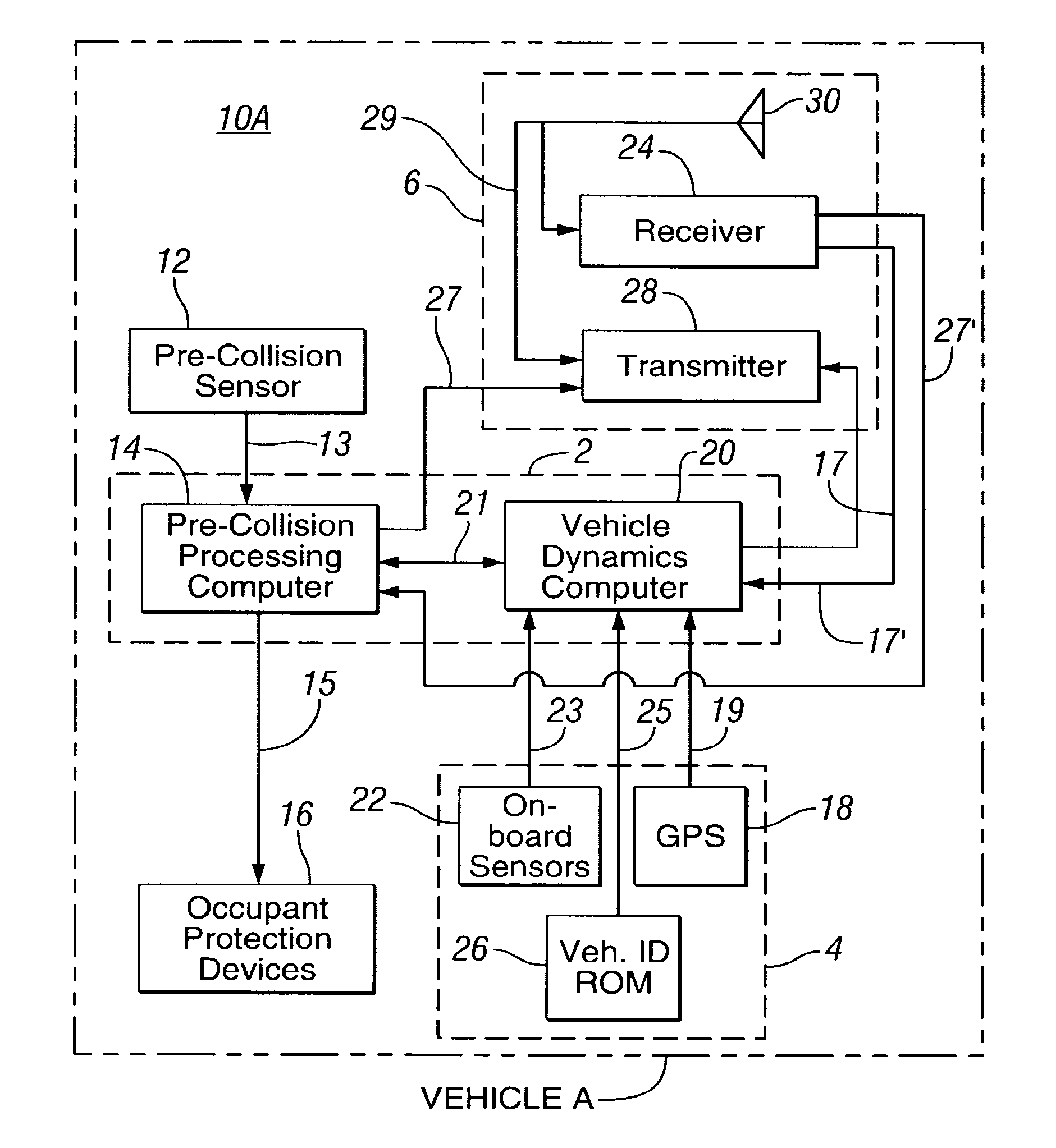
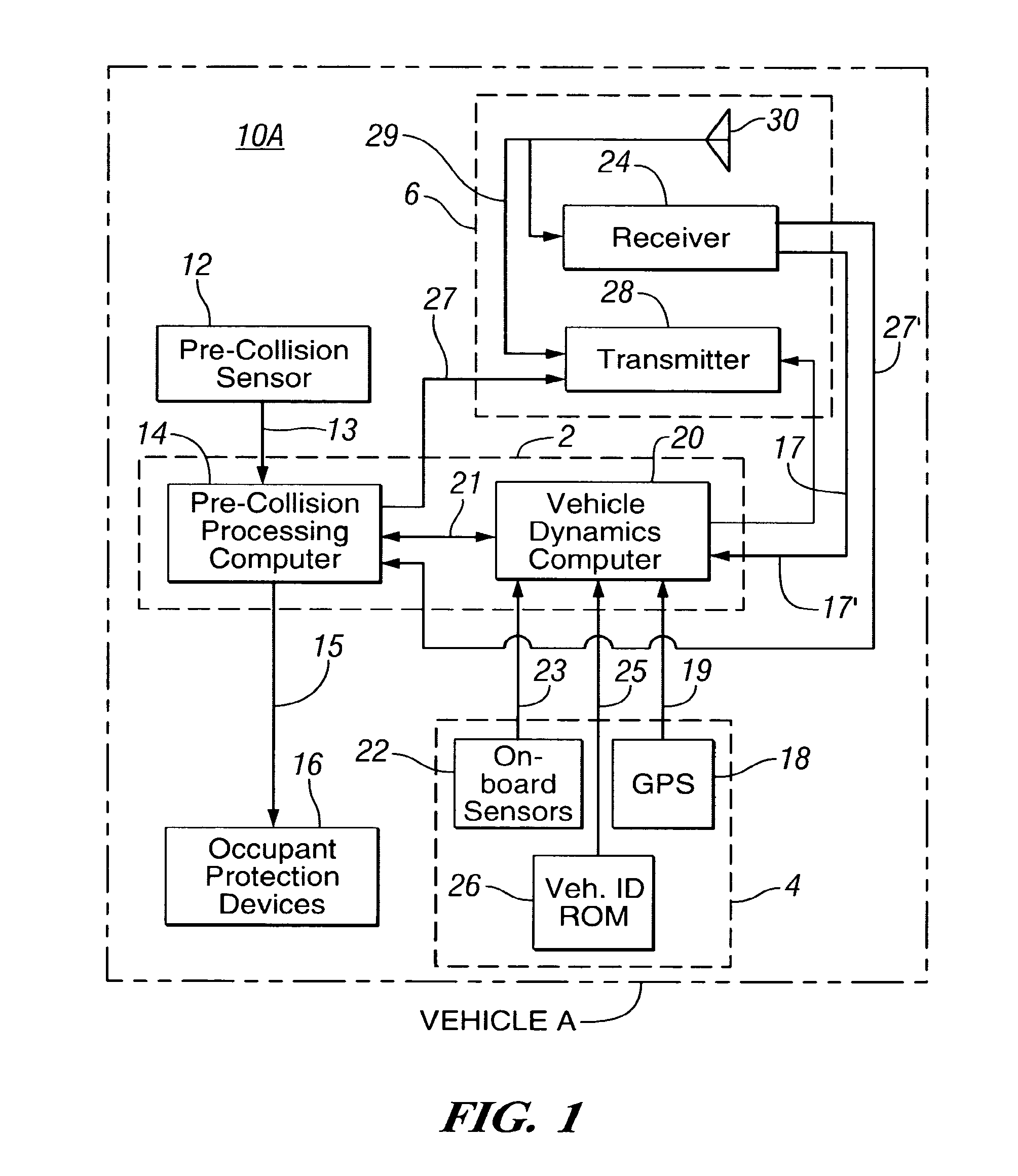
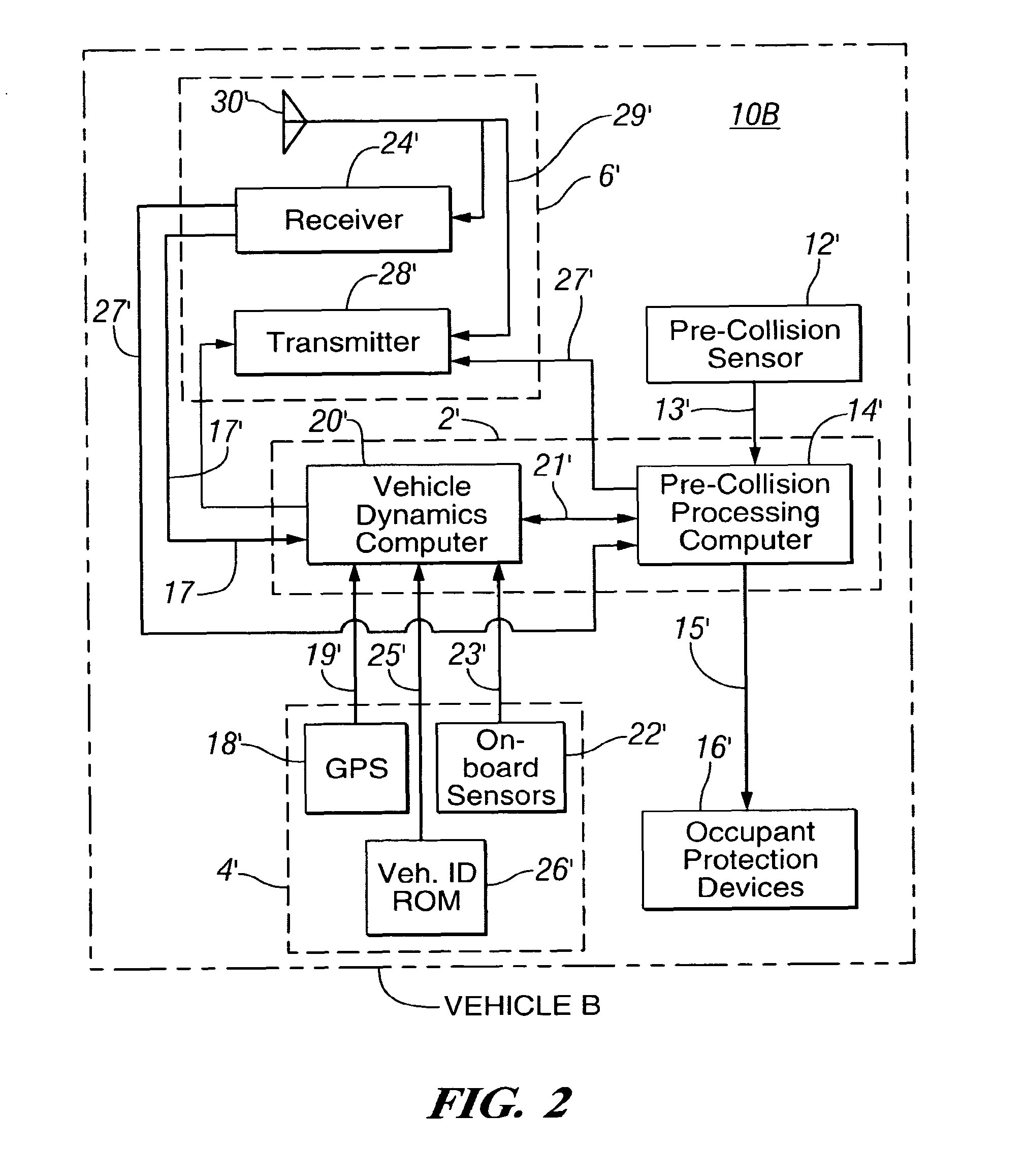
[0012]In accordance with exemplary embodiments of the present invention, a method is provided which predicts the severity of an imminent or nearly imminent potential collision of two vehicles. The prediction is based upon robust vehicle condition-defining information about both vehicles. The vehicle condition-defining information about both vehicles is developed after it is detected that the collision is likely to occur and / or imminent. Alternatively, all or a subset of the vehicle condition-defining information for each vehicle is continuously developed while the vehicle is in operation and available for use in the prediction. Further, the prediction of potential collision severity is developed so that occupant safety devices can be deployed in accordance with the predicted potential collision severity. Referring now to the drawings, there is shown an illustrative embodiment of the invention which is adapted for use in controlling the deployment of passenger protection devices in l...


PUM


Abstract

A method of predicting severity of a potential collision of first and second vehicles. The method includes determining that a probability of a potential collision of the vehicles is greater than a threshold value. Vehicle condition-defining signals are exchanged between the vehicles when the probability of the potential collision is greater than the threshold value including a first vehicle condition-defining signal developed on board the first vehicle and a second vehicle condition-defining signal developed onboard the second vehicle. The method further includes predicting onboard the first vehicle a severity of the potential collision for the first vehicle based upon input that includes the first vehicle condition-defining signal and the second vehicle condition-defining signal. A severity of the potential collision for the second vehicle is predicted onboard the second vehicle based upon the second vehicle condition-defining signal and the first vehicle condition-defining signal.

Description

CROSS REFERENCE TO RELATED APPLICATIONS[0001]This application is a divisional of U.S. patent application Ser. No. 10 / 823,391 filed Apr. 13, 2004, which is a continuation-in-part of U.S. patent application Ser. No. 10 / 355,688 filed on Jan. 31, 2003, which is a continuation of U.S. patent application Ser. No. 09 / 782,461 filed on Jan. 22, 2001; and which is now issued as U.S. Pat. No. 6,571,161 issued May 27, 2003; and all of the above-mentioned patents and patent applications are incorporated by reference herein in their entirety.TECHNICAL FIELD[0002]The present disclosure relates generally to pre-collision warning / detection systems for road vehicles. More particularly, it relates to a system for robustly assessing the expected severity of a potential collision of two vehicles.BACKGROUND OF THE INVENTION[0003]Currently-available pre-collision warning / detection systems do not distinguish between two vehicles which are about the same size but which have significantly different mass and ...

Claims


Application Information

Patent Timeline
Patent Type & Authority Patents(United States)
IPC IPC(8): G05D1/00G06F7/00G01S13/86G01S13/87G01S13/931
CPCB60R21/013G01S13/86G01S13/87G01S13/931B60R21/0134B60R2021/01088G01S2013/9353G01S2013/9357G01S2013/9322G01S2013/932
Inventor BROWNE, ALAN LWOOD, FRANCIS DALTAN, OSMAN D
Owner GM GLOBAL TECH OPERATIONS LLC
Learn More