Oscillating positive expiratory pressure device

a positive, expiratory pressure technology, applied in the direction of gymnastic exercise, valve operating means/release devices, sport apparatus, etc., can solve the problems of affecting the bronchial obstruction, splitting open obstructed airways, and insufficient single cough to clear obstructions

Active Publication Date: 2012-12-11
TRUDELL MEDICAL INT INC
View PDF112 Cites 59 Cited by
  • Summary
  • Abstract
  • Description
  • Claims
  • Application Information

AI Technical Summary

Problems solved by technology

However, for individuals suffering from more significant bronchial obstructions, such as collapsed airways, a single cough may be insufficient to clear the obstructions.
It is believed that OPEP therapy, or the oscillation of exhalation pressure at the mouth during exhalation, effectively transmits an oscillating back pressure to the lungs, thereby splitting open obstructed airways and loosening the secretions contributing to bronchial obstructions.

Method used


Image

  • Oscillating positive expiratory pressure device
  • Oscillating positive expiratory pressure device
  • Oscillating positive expiratory pressure device

Examples


first embodiment

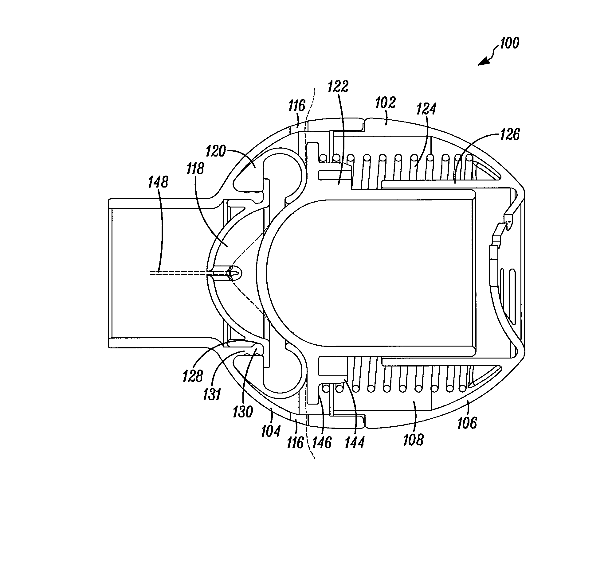
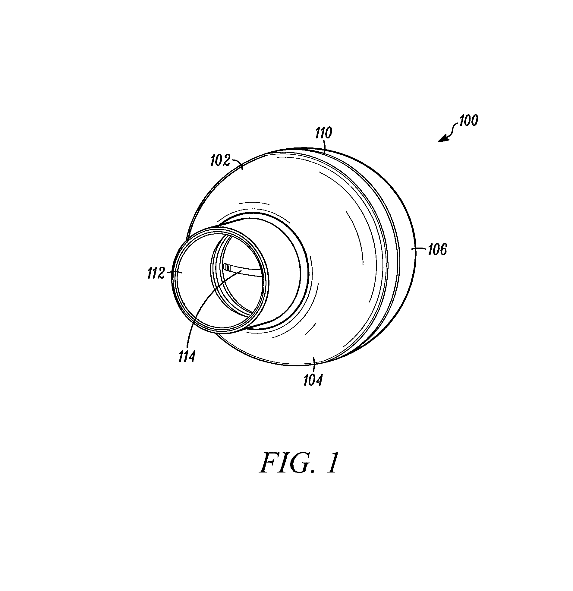
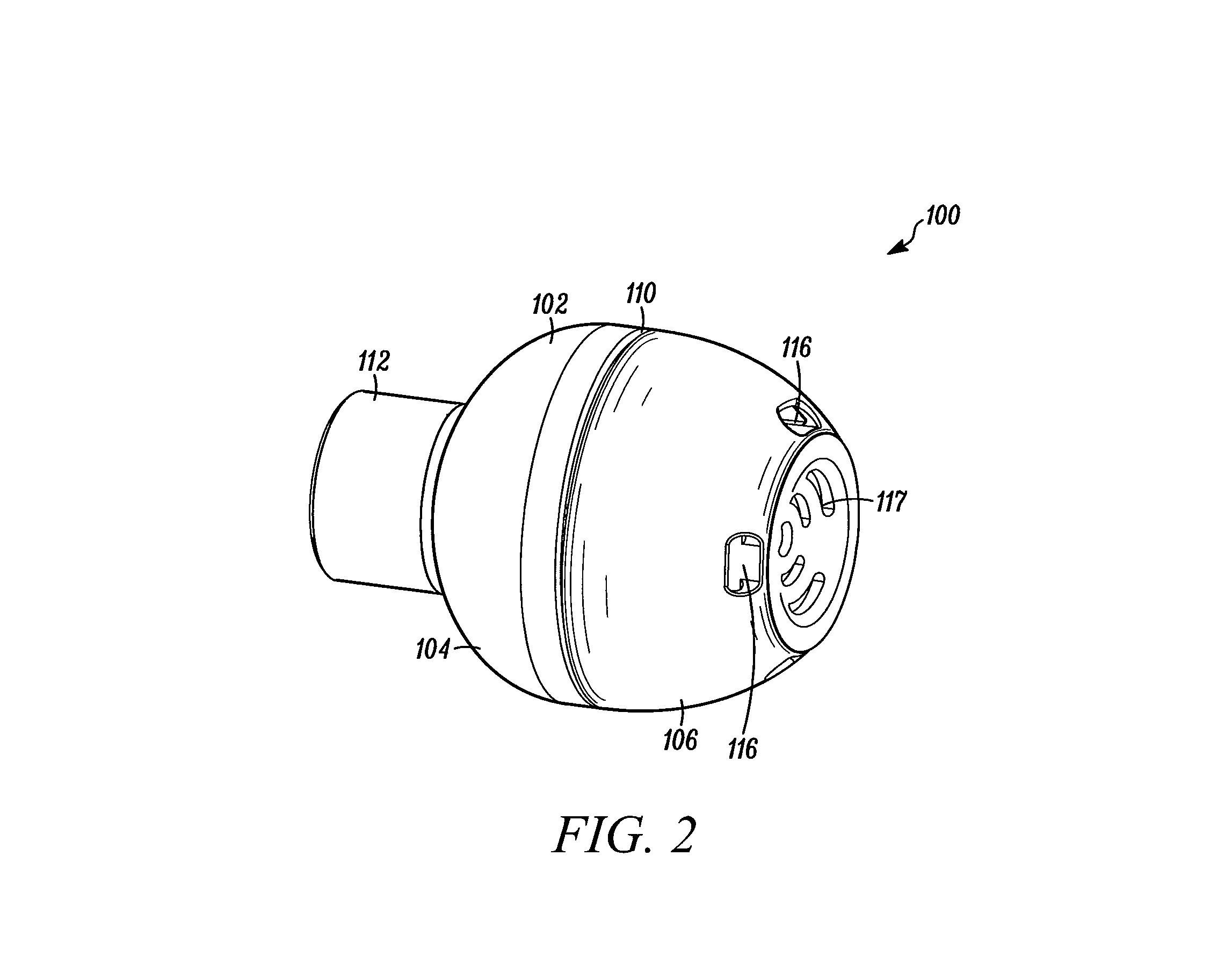
[0030]Referring to FIG. 1, an assembled OPEP device 100 is shown. The OPEP device 100 comprises a housing 102 having a front portion 104 and a rear portion 106 which together defines a chamber 108 (see FIG. 3). The housing 102 may be constructed of any durable material, such as a plastic or a metal. The OPEP device 100 shown in FIG. 1 is substantially spherical in shape, which provides for an easy grasp of the OPEP device 100 in the hands of a user, as well as portability. It should be appreciated, however, that the OPEP device 100 could be any shape, so long as it defines a chamber 108 capable of housing the necessary components, as described herein. Preferably, the housing 102 is openable so the chamber 108 may be accessed for cleaning and replacing components contained therein. As shown, the front portion 104 and the rear portion 106 of the housing 102 are removably connected along a joint 110, such as by a snap fit or a threaded screw connection.

[0031]The OPEP device 112 also in...

second embodiment

[0048]A cross-sectional side view of an OPEP device 200 is shown in FIG. 8. Like the OPEP device 100, a housing 202 of the OPEP device 200 encloses a deformable restrictor member 220, an oscillation member 222, a coil spring 224, and a glide surface 226. The OPEP device 200 also includes a mouthpiece 212, a chamber inlet 214, a chamber outlet 216, and has an exhalation flow path 248 defined therebetween.

[0049]The OPEP device 200 further comprises an adjustment plate 254 for selectively moving an end of a biasing member, such as the coil spring 224, to adjust the amount of bias. The adjustment plate 254 is connected to at least one thumb screw 256 extending from the adjustment plate 254 to a location outside the housing 202. In this way, a user may rotate the at least one thumb screw 256 in one direction to move both the adjustment plate 254 and an end of the coil spring 224 toward the oscillation member 222, thereby increasing the bias. A user may rotate the at least one thumb screw...

third embodiment

[0053]A cross-sectional perspective view of an OPEP device 300 is shown in FIG. 13. In general, a housing 302 of the OPEP device 300 encloses a deformable restrictor member 320, an oscillation member 322 having a one-way valve 352, a glide surface 326, and an adjustment plate 354. The OPEP device 300 also includes a mouthpiece 312, a chamber inlet 314, a chamber outlet 316, and a respiratory portal 350.

[0054]The OPEP device 300 is different from the OPEP device 200 in that it includes a biasing member comprised of at least one pair of magnets 362. For each pair of the at least one pair of magnets 362, one magnet is positioned on the oscillation member 322 and another magnet is positioned on the adjustment plate 354. The magnets in each pair have opposing polarities. As such, the oscillation member 322 is biased by the at least one pair of magnets 362 into the engaged position with the deformable restrictor member 320.

[0055]During the administration of OPEP therapy, the at least one ...


PUM


Abstract

An oscillating positive expiratory pressure apparatus having a housing defining a chamber, a chamber inlet, a chamber outlet, a deformable restrictor member positioned in an exhalation flow path between the chamber inlet and the chamber outlet, and an oscillation member disposed within the chamber. The deformable restrictor member and the oscillation member are moveable between an engaged position, where the oscillation member is in contact with the deformable restrictor member and an disengaged position, where the oscillation member is not in contact with the deformable restrictor member. The deformable restrictor member and the oscillation member move from the engaged position to the disengaged position in response to a first exhalation pressure at the chamber inlet, and move from the disengaged position to an engaged position in response to a second exhalation pressure at the chamber inlet.

Description

RELATED APPLICATIONS[0001]This application claims the benefit of U.S. Provisional Application No. 61 / 109,075, filed on Oct. 28, 2008, pending, which is incorporated herein by reference.TECHNICAL FIELD[0002]The present disclosure relates to an expiratory treatment device, and in particular, to an oscillating positive expiratory pressure (“OPEP”) device.BACKGROUND[0003]Each day, humans may produce upwards of 30 milliliters of sputum, which is a type of bronchial secretion. Normally, an effective cough is sufficient to loosen secretions and clear them from the body's airways. However, for individuals suffering from more significant bronchial obstructions, such as collapsed airways, a single cough may be insufficient to clear the obstructions.[0004]OPEP therapy represents an effective bronchial hygiene technique for the removal of bronchial secretions in the human body and is an important aspect in the treatment and continuing care of patients with bronchial obstructions, such as those ...

Claims


Application Information

Patent Timeline
Patent Type & Authority Patents(United States)
IPC IPC(8): A62B9/02
CPCA61M16/208A61M16/0057A61M16/0006A61M16/14Y10S137/908A61M16/0866A61M11/02A61M16/06A61M16/0816A61M2205/10
Inventor FOLEY, MARTIN P.GRYCHOWSKI, JERRY
Owner TRUDELL MEDICAL INT INC
Why Eureka
Try Eureka