Dental implant

a technology for dental implants and abutments, applied in dentistry, dental prosthetics, medical science, etc., can solve the problem of inaccurate reference of the position of the abutment, and achieve the effect of avoiding the application of impulsive forces and easing the disconnection of the abutmen

Active Publication Date: 2012-12-11
LEONE SPA
View PDF21 Cites 7 Cited by
  • Summary
  • Abstract
  • Description
  • Claims
  • Application Information

AI Technical Summary

Benefits of technology

[0006]One object of the present invention is to propose a dental implant able to ease the disconnection of the abutment from the fixture, thereby avoiding the application of impulsive forces.
[0007]A further object of the present invention is to propose a dental implant which allows maintaining a precise reference for the position of the abutment relative to the fixture.
[0009]The present invention makes it possible to make a dental implant with self-blocking / self-locking Morse-taper coupling which, therefore, allows reducing the gap between the coupled surfaces of the abutment and fixture to a minimum, while maintaining or restoring all the time also the correct mutual orientation of these two elements and facilitating the disconnection thereof even after a prolonged period of permanent coupling. Moreover, a dental implant according to the present invention is relatively easy to make and reliable even after a long service period.

Problems solved by technology

On the other hand, when the abutment is not provided with an appendix of polygonal cross-section type, there is no accurate reference for the position of the abutment, with respect to the fixture, during both the preparation of the prosthesis and the fitting tests of the implant on the patient.

Method used


Image

  • Dental implant
  • Dental implant
  • Dental implant

Examples


Embodiment Construction

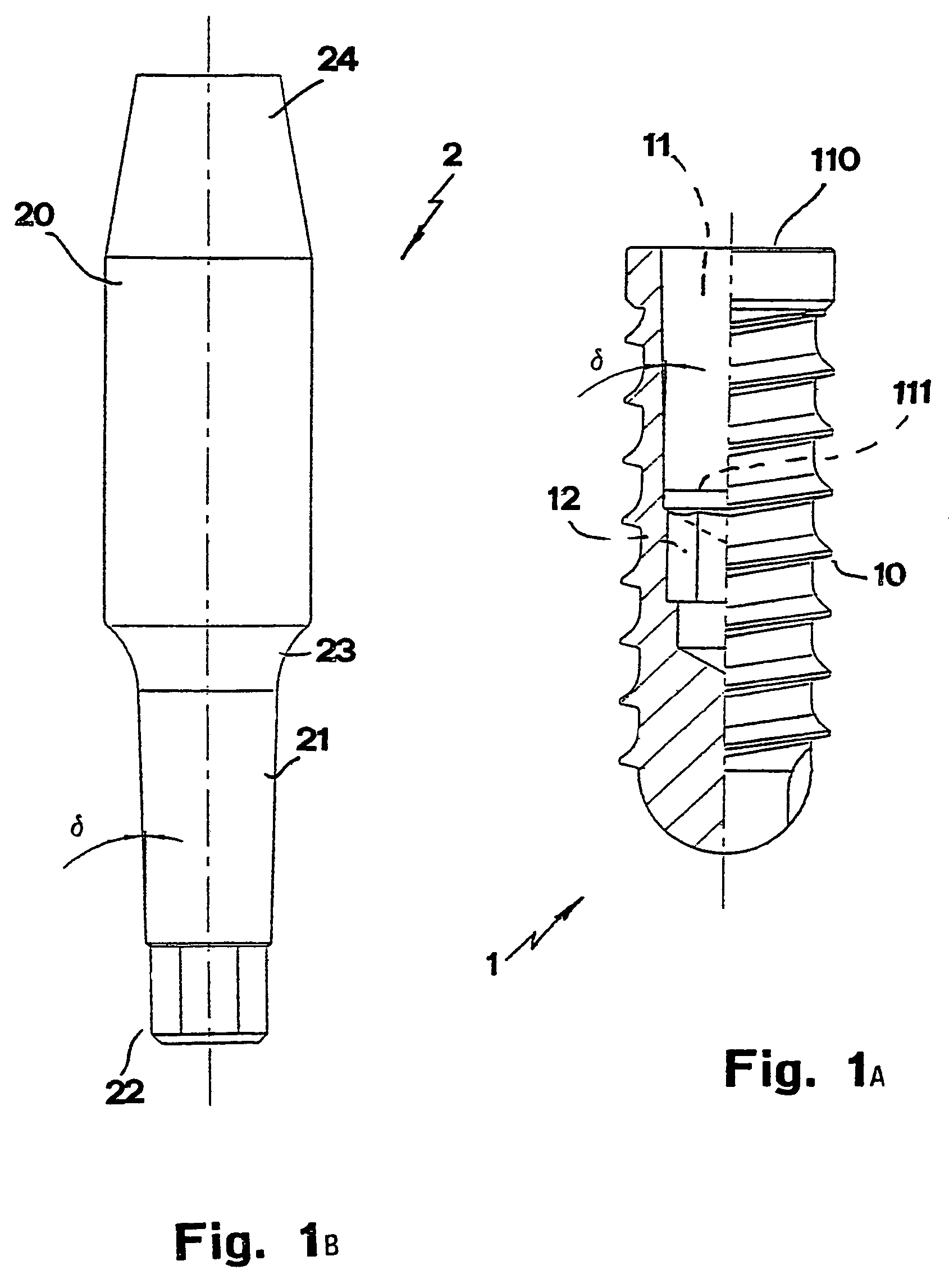
[0028]Reduced to its basic structure, and reference being made to the figures of the attached drawings, a dental implant according to the present invention is of a type comprising an artificial root or fixture (1) and a stump or abutment (2).

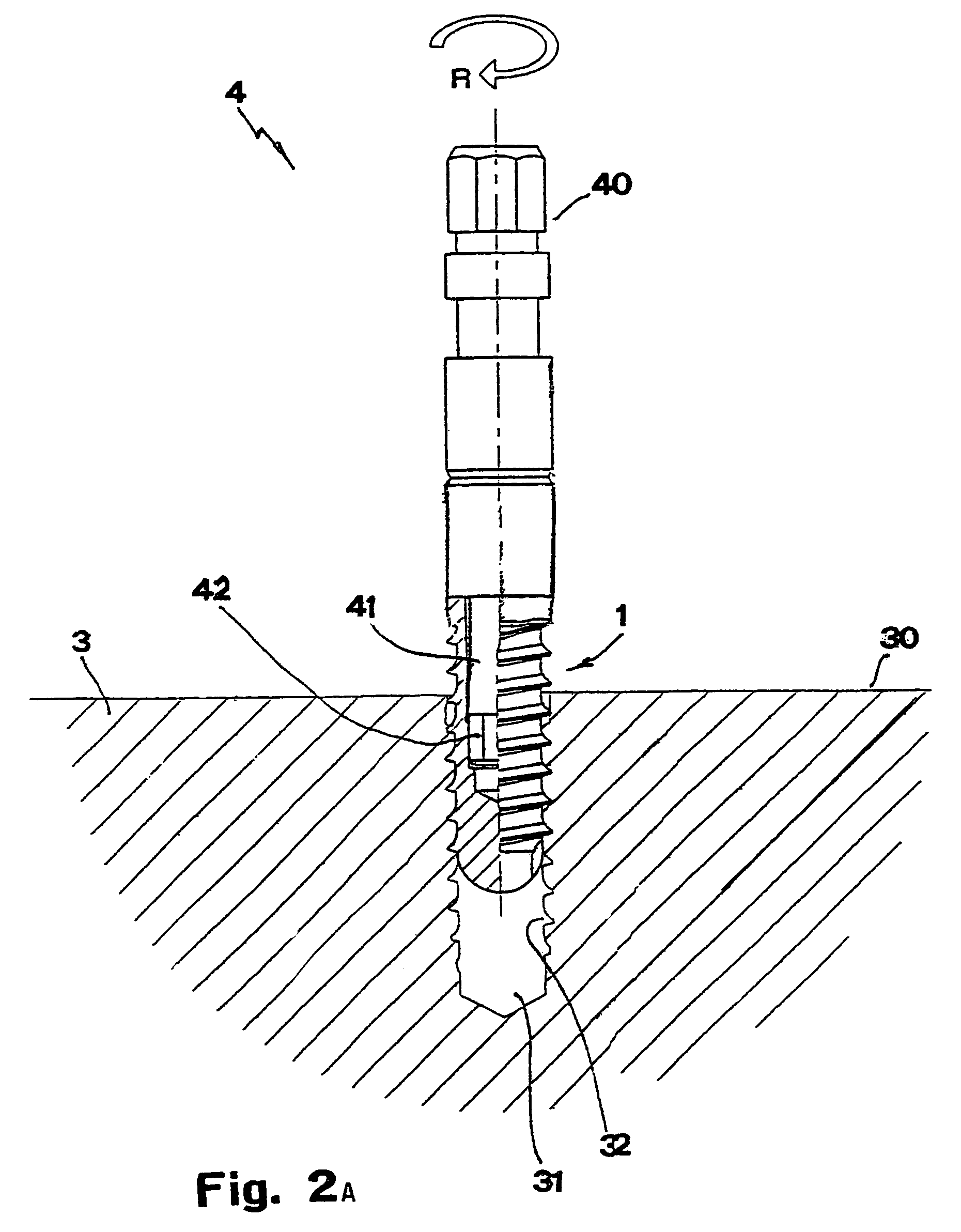
[0029]The fixture (1) is to be implanted in the subgingival bony tissue (3) in correspondence of a missing tooth. According to the example shown in the drawings, the said fixture (1) comprises a body with external threading (10), an internal cavity (11) and a seat (12) with polygonal cross-section—for example, hexagonal—on the bottom of said cavity (11). The latter has a truncated-cone development, with the major base (110) up and the minor base (111) down. The half angle (6) of the cone has a preset value, for example, a nominal value of 1.5°.

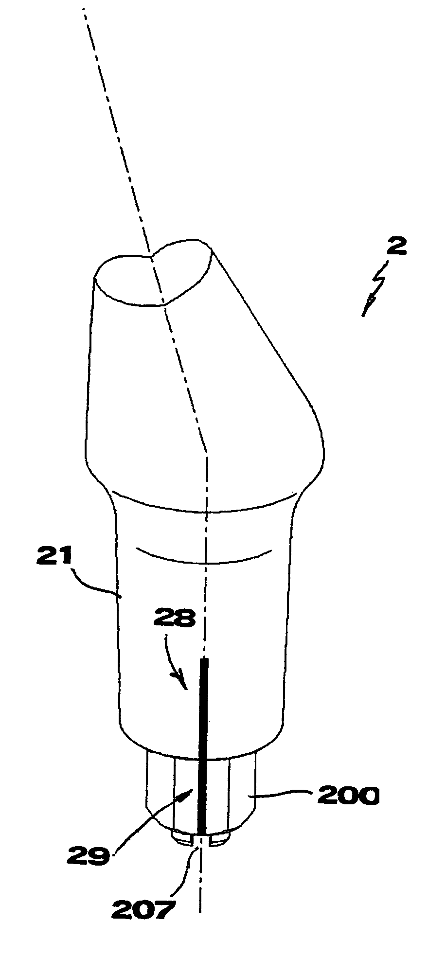
[0030]According to the exemplary embodiments shown in the attached drawings, the said abutment (2) comprises a body with an upper, or coronal, part (20) terminating with a substantially truncated-cone face...


PUM


Abstract

An abutment (2) connects with a fixture (1) by a Morse-taper type coupling, with the installation of a truncated-cone shank (21) of the abutment (2) into a corresponding cavity (11) exhibited by the fixture (1). The abutment (2) is provided with an appendix having a polygonal cross-section (22), and is positioned below the shank (21). The appendix is fitted into a corresponding impression (12) provided in the bottom of the cavity (11) of fixture (1). The abutment is also provided, on the side opposite to the appendix (22), with respect to the shank (21), with a portion (20, 24) intended for supporting a dental prosthesis (D). The appendix (22) can be rotated about its longitudinal axis, relative to the shank (21) of the abutment (2).

Description

FIELD OF THE INVENTION[0001]The present invention relates to a dental implant.BACKGROUND OF THE INVENTION[0002]A dental implant is known to make up for the loss of one or more dental element, and to consist of one or more components intended to restore both the masticatory function and the aesthetic aspect.[0003]In general, a dental implant comprises an artificial root or fixture to be implanted surgically in the bony tissue, and a stump or abutment intended for supporting a dental prosthesis and connected to the fixture. The abutment is connected to the fixture after a preset time allowing the correct execution of an osteo-integration process by which the fixture results afterwards integrated in the bony tissue. The fixture is generally provided with an outer threading to allow it to be screwed into the bony tissue, but it can also be shaped in a different way in order to be inserted by pressure into the implant seat.[0004]More particularly, dental implants are known in which a cou...

Claims


Application Information

Patent Timeline
Patent Type & Authority Patents(United States)
IPC IPC(8): A61C13/12A61C13/225A61C8/00
CPCA61C8/005A61C8/006A61C8/0066A61C8/0069A61C8/0074A61C8/0071
Inventor SCOMMEGNA, GABRIELEDOLFI, MAURIZIO
Owner LEONE SPA
Why Eureka
Try Eureka