Connector improved in handlability of a connection object and backlight assembly using the connector

a technology of connectors and connector objects, applied in the field of connectors, can solve the problems of increased cost, large number of operation steps, and large number of components used, and achieve the effect of improving the handlability of the connection object and facilitating the connection and disconnection of the connection obj

Inactive Publication Date: 2009-07-07
JAPAN AVIATION ELECTRONICS IND LTD
View PDF4 Cites 15 Cited by
  • Summary
  • Abstract
  • Description
  • Claims
  • Application Information

AI Technical Summary

Benefits of technology

[0011]It is therefore an exemplary object of this invention to provide a connector which is improved in handlability of a connection object and which makes it easy to connect and disconnect the connection object.
[0012]It is another exemplary object of this invention to provide a connector which is improved in handlability of a lamp tube and which makes it easy to connect and disconnect the lamp tube.
[0013]It is still another exemplary object of this invention to provide a backlight assembly which requires a small number of components so that the number of assembling steps is reduced and the cost is lowered.

Problems solved by technology

Therefore, a large number of components are used and a large number of operation steps is required.
This brings about an increase in cost.
In addition, the lamp tube with the cable soldered thereto is easily broken during handling.
However, various kinds of stresses are caused to occur, for example, a stress generated during contact due to a positioning error at assembling of the lamp tube and the connector, a stress of vibration or mechanical shock applied during transportation or during use of a liquid crystal assembly, or a stress due to heat shrinkage of the lamp tube resulting from heat generation of the lamp tube itself.
These stresses concentrate to the lead wire of the lamp tube or a lead wire sealing portion and may result in breakage of the lamp tube or a shortened lifetime of the lamp tube.
However, the techniques disclosed in these publications can not solve the above-mentioned problems.
However, these techniques are disadvantageous in that a large number of components and a high cost are required.

Method used


Image

  • Connector improved in handlability of a connection object and backlight assembly using the connector
  • Connector improved in handlability of a connection object and backlight assembly using the connector
  • Connector improved in handlability of a connection object and backlight assembly using the connector

Examples


exemplary embodiment 1

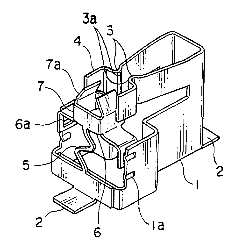
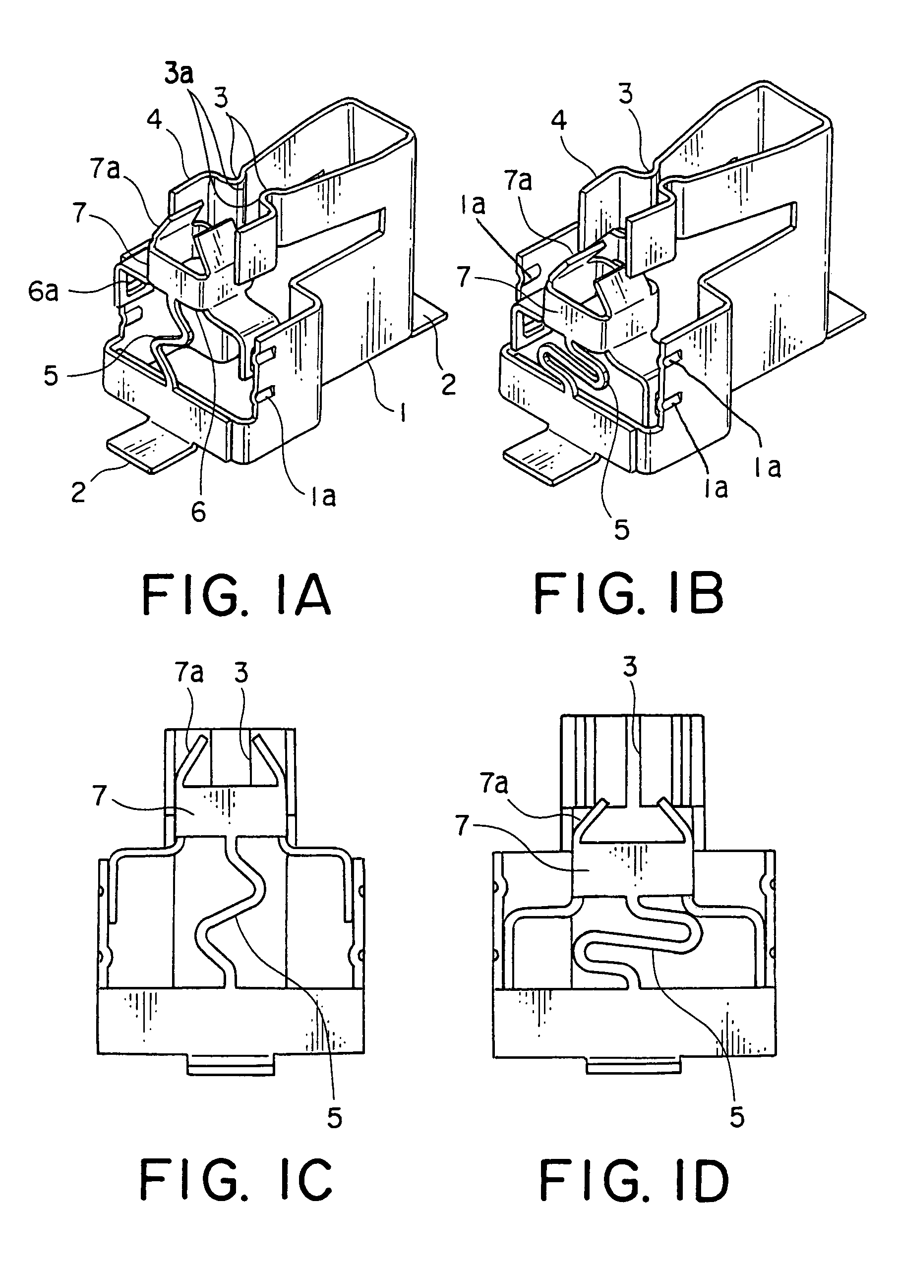
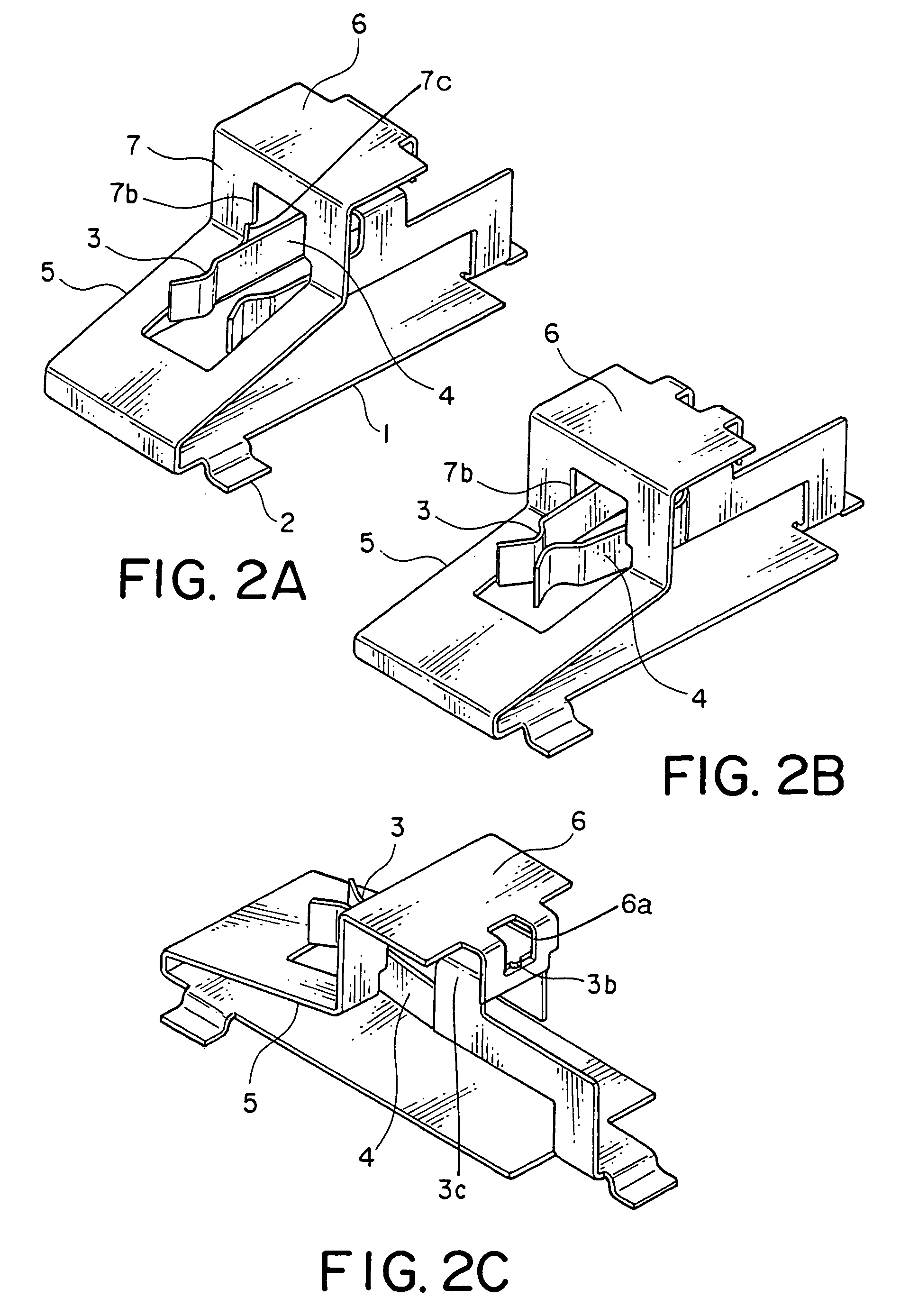
[0078]2. The connector , wherein the conductive member comprises:

[0079]a main body 1 integrally formed with the contacting portion 3; and

[0080]an elastic portion 5 coupling the position control portion 6 to the main body 2 so that the position control portion 6 is displaceable with respect to the main body 1.

exemplary embodiment 2

[0081]3. The connector , wherein the main body 1 includes an engaging portion 1a for engaging the position control portion 6.

[0082]4. The connector according to exemplary embodiment 2, wherein the contacting portion 3 includes an engaging portion 1a for engaging the position control portion 6.

[0083]5. The connector according to exemplary embodiment 1, wherein the conductive member comprises:

[0084]a main body 1 integrally formed with the position control portion 6; and

[0085]an elastic portion 5 coupling the contacting portion 3 to the main body 1 so that the contacting portion 3 is displaceable with respect to the main body 1.

exemplary embodiment 5

[0086]6. The connector , wherein the contacting portion 3 is kept by the elastic portion 5 at an inoperative position of the position control portion 6.


PUM


Abstract

In a connector including a conductive member adapted to be connected to a connection object, the conductive member includes a movable contacting portion to be contacted with the connection object and a position control portion integrally formed with the contacting portion and serving to control a position of the contacting portion. The contact may includes a main body integrally formed with the contacting portion and an elastic portion coupling the position control portion to the main body so that the position control portion is displaceable with respect to the main body. The main body may be integrally formed with the position control portion. The elastic portion may couple the contacting portion to the main body so that the contacting portion is displaceable with respect to the main body.

Description

[0001]This application claims priority to prior Japanese patent applications JP 2006-338885 and JP 2007-10513, the disclosures of which are incorporated herein by reference.BACKGROUND OF THE INVENTION[0002]This invention relates to a connector, such as a direct type lamp socket, adapted to connect a lamp tube and to a backlight assembly using the connector.[0003]Recently, a large-sized liquid crystal display is widely used in various technical fields. A backlight module used in the large-sized liquid crystal display comprises a small-diameter lamp tube, such as CCFL (cold cathode fluorescent lamp) and EEFL (external electrode fluorescent lamp), as a light source. A system in which a liquid crystal glass is irradiated directly by a light from the lamp tube located behind the liquid crystal glass is called a direct type. The direct-type system is excellent in light utilization efficiency and is most suitable for a backlight of a liquid crystal display, such as a monitor and a televisi...

Claims


Application Information

Patent Timeline
Patent Type & Authority Patents(United States)
IPC IPC(8): H01R29/00
CPCH01R33/02H01R13/193
Inventor KATO, RINTAROKATO, NOBUKAZUKIMURA, AKIRAKUROIWA, MASAKAZU
Owner JAPAN AVIATION ELECTRONICS IND LTD
Why Eureka
Try Eureka