Cable connector joint fastening structure

Inactive Publication Date: 2012-12-11
QUANTUM PRECISION TECH
View PDF7 Cites 31 Cited by
  • Summary
  • Abstract
  • Description
  • Claims
  • Application Information

AI Technical Summary

Benefits of technology

[0005]Therefore, it is a primary objective of the present invention to provide a cable connector joint fastening structure, wherein male and female connectors of the connector are locked with one another, while a locking component is installed across a screw sleeve fo

Problems solved by technology

However, the enhanced connection structure of the conventional cable connector still has the drawbacks of being loosened easily or affecting the functions of present existing installed components, and thus its appearance and structure must be redesigned and such cable connector is not applicable for a particular model only.
For example, a conductive terminal connecting device as discl

Method used


Image

  • Cable connector joint fastening structure
  • Cable connector joint fastening structure
  • Cable connector joint fastening structure

Examples


Embodiment Construction

[0015]The technical characteristics and contents of the present invention will become apparent with the following detailed description and related drawings. The drawings are provided for the purpose of illustrating the present invention only, but not intended for limiting the scope of the invention.

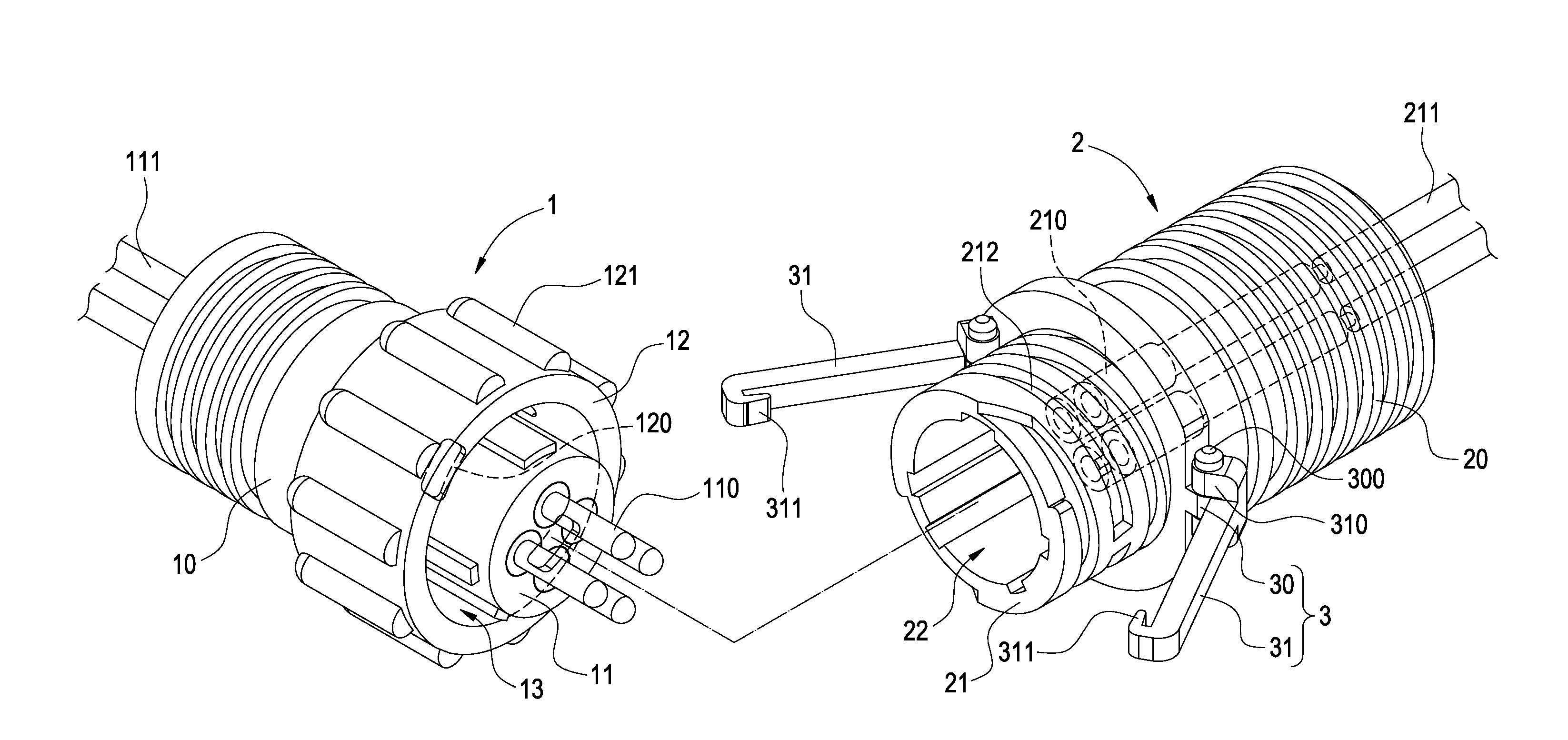
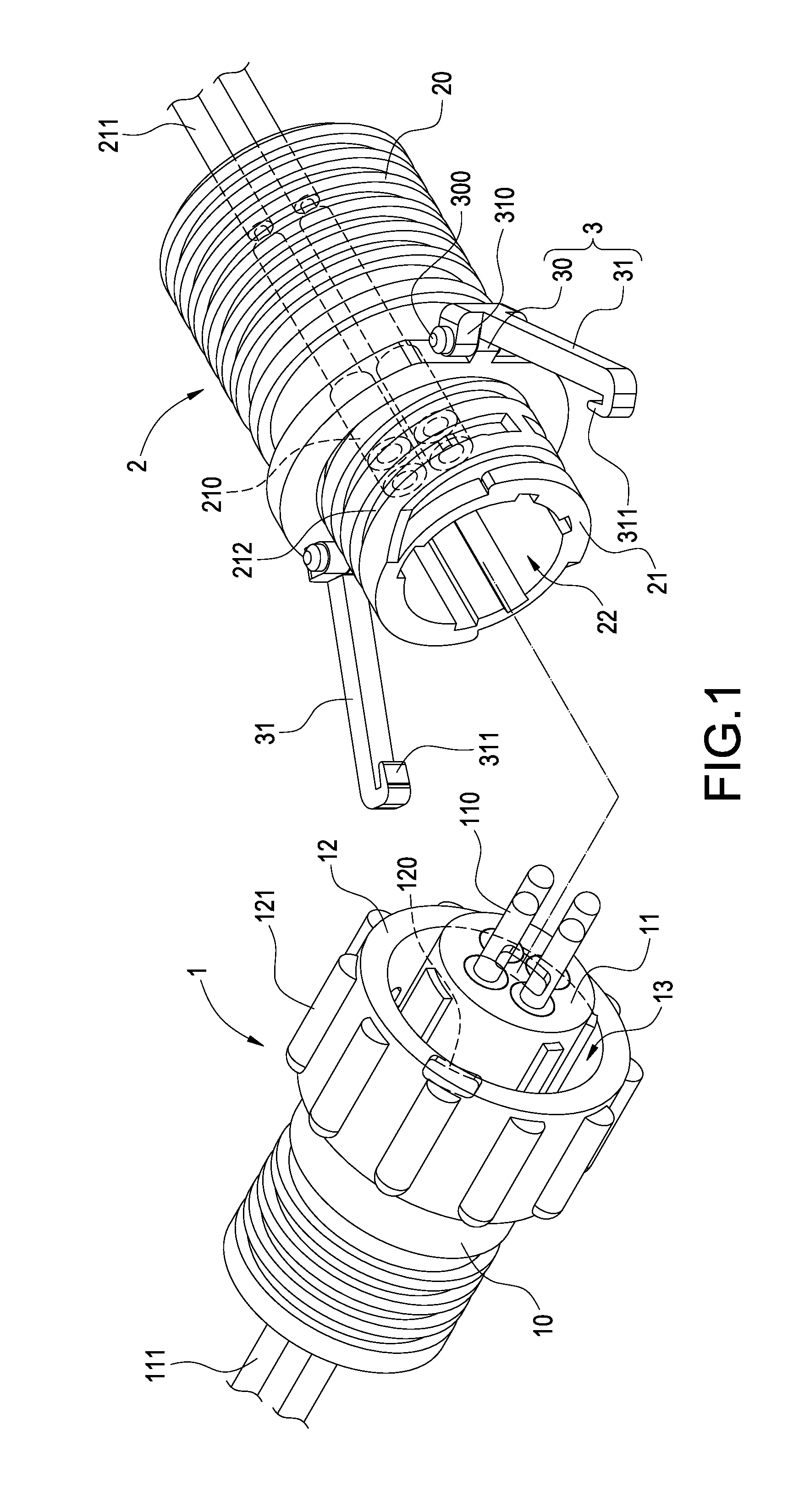
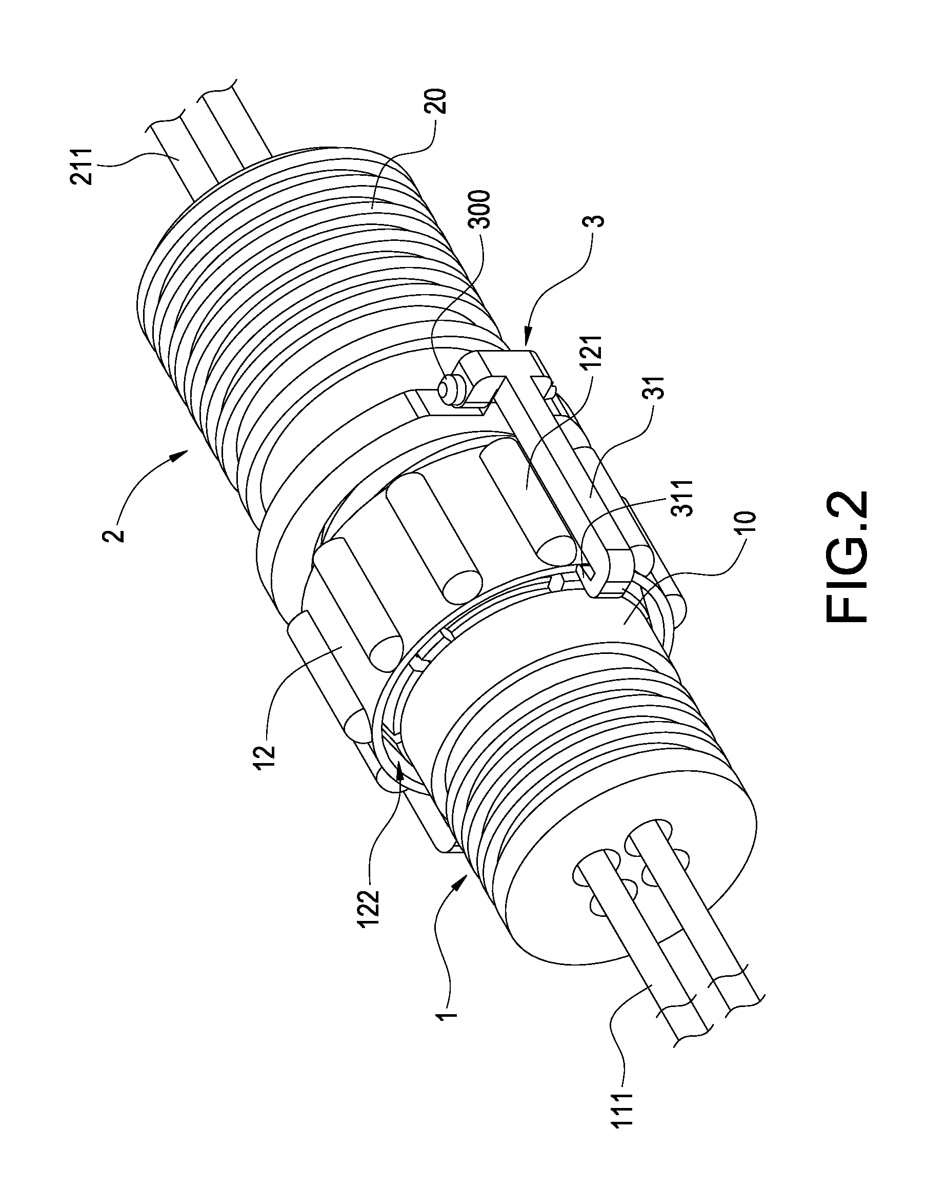
[0016]With reference to FIGS. 1 and 2 for an exploded view and a perspective view of a first preferred embodiment of the present invention respectively, the invention provides a cable connector joint fastening structure comprising a male connector 1, a female connector 2, and at least one fastener 3.

[0017]The male connector 1 includes a cylindrical male terminal body 10, a male terminal joint 11 protruded from a front end of the male terminal body 10, and a plurality of male terminals 110 disposed in the male terminal joint 11. Each male terminal 110 is extended to an end of the male terminal body 10 and electrically coupled to each wire core 111 in the cable (not shown in the figure). In...


PUM


Abstract

A cable connector joint fastening structure includes a male connector, a female connector, and a fastener. The male connector includes a male terminal body with a male terminal joint, a freely rotating screw sleeve locked around the external periphery of the male terminal joint. The female connector includes a female terminal body with a female terminal joint, and an insert space formed in the female terminal joint for inserting the male terminal joint, and the screw sleeve is screwed and coupled to the female terminal joint. The fastener includes a pivot portion formed at an external side of the female connector, and a locking arm pivotally installed onto the pivot portion, extended towards the male terminal body, disposed across the screw sleeve, and locked to the male connector.

Description

FIELD OF THE INVENTION[0001]The present invention relates to a connector, in particular to a cable connector joint fastening structure.BACKGROUND OF THE INVENTION[0002]In a conventional cable connector, male and female connectors are provided for achieving the effect of connecting the cable connector, and an enhanced connection structure is generally deigned for improving the insertability or connectivity of the connectors and assuring a secured connection of the male and female connectors to prevent them from being loosened or separated.[0003]However, the enhanced connection structure of the conventional cable connector still has the drawbacks of being loosened easily or affecting the functions of present existing installed components, and thus its appearance and structure must be redesigned and such cable connector is not applicable for a particular model only. For example, a conductive terminal connecting device as disclosed in Taiwan Pat. No. M391748 includes a locking hook lock...

Claims


Application Information

Patent Timeline
IPC IPC(8): H01R4/38
CPCH01R13/6275H01R13/639H01R13/622H01R9/03H01R13/64
Inventor LIN, CHIH-CHENG
Owner QUANTUM PRECISION TECH
Why Eureka
Try Eureka