
Audio mixing

a technology of audio signals and mixing methods, applied in the direction of electrical transducers, special services for subscribers, transducer details, etc., can solve the problems of reducing the signal to noise ratio, reducing the quality, and reducing the complexity of mixing and encoding, so as to avoid the annoying switching behavior in background noise in some situations

Active Publication Date: 2012-12-11
GOOGLE LLC
View PDF11 Cites 247 Cited by
  • Summary
  • Abstract
  • Description
  • Claims
  • Application Information

AI Technical Summary

Benefits of technology

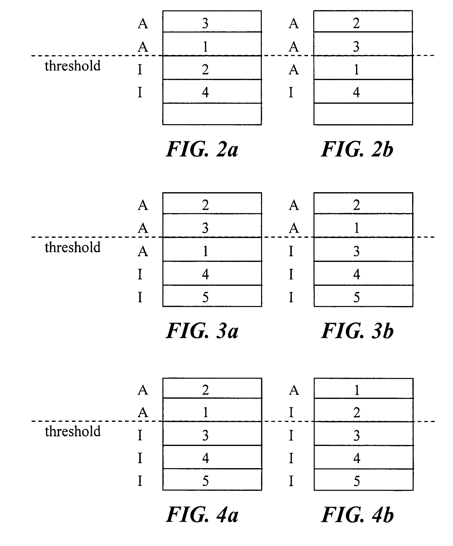
The present invention provides a method and apparatus for mixing audio signals based on their dynamic behavior, rather than relying on quantitative measures. The method involves arranging a set of audio channels in a mixing stack and producing a mixed audio signal from the topmost channels. When a new channel becomes active, it is placed at the top of the stack, ensuring that it is always part of the mixed audio output signal. This avoids annoying switching behavior in the background noise and allows for easy joining of new users in a conference without relying on their ranking. The invention can be used for speech conferences or any other audio sources.

Problems solved by technology

This saves complexity both in mixing and encoding.
This is because mixing of too many channels, of which some only contain background noise, will degrade quality, as it will degrade the signal to noise ratio of the resulting mixed signal.
One problem with this prior art is the difficulty for a new audio stream to be included in the mix of audio streams.
Another problem with the above described prior art is that such a scheme for mixing audio streams in certain common situations will result in an annoying switching behaviour in the background noise.
This problem will be output signal.
This in turn will result in annoying switching behaviour in the background noise of the mixed output signal.

Method used


Image

  • Audio mixing
  • Audio mixing
  • Audio mixing

Examples


Embodiment Construction

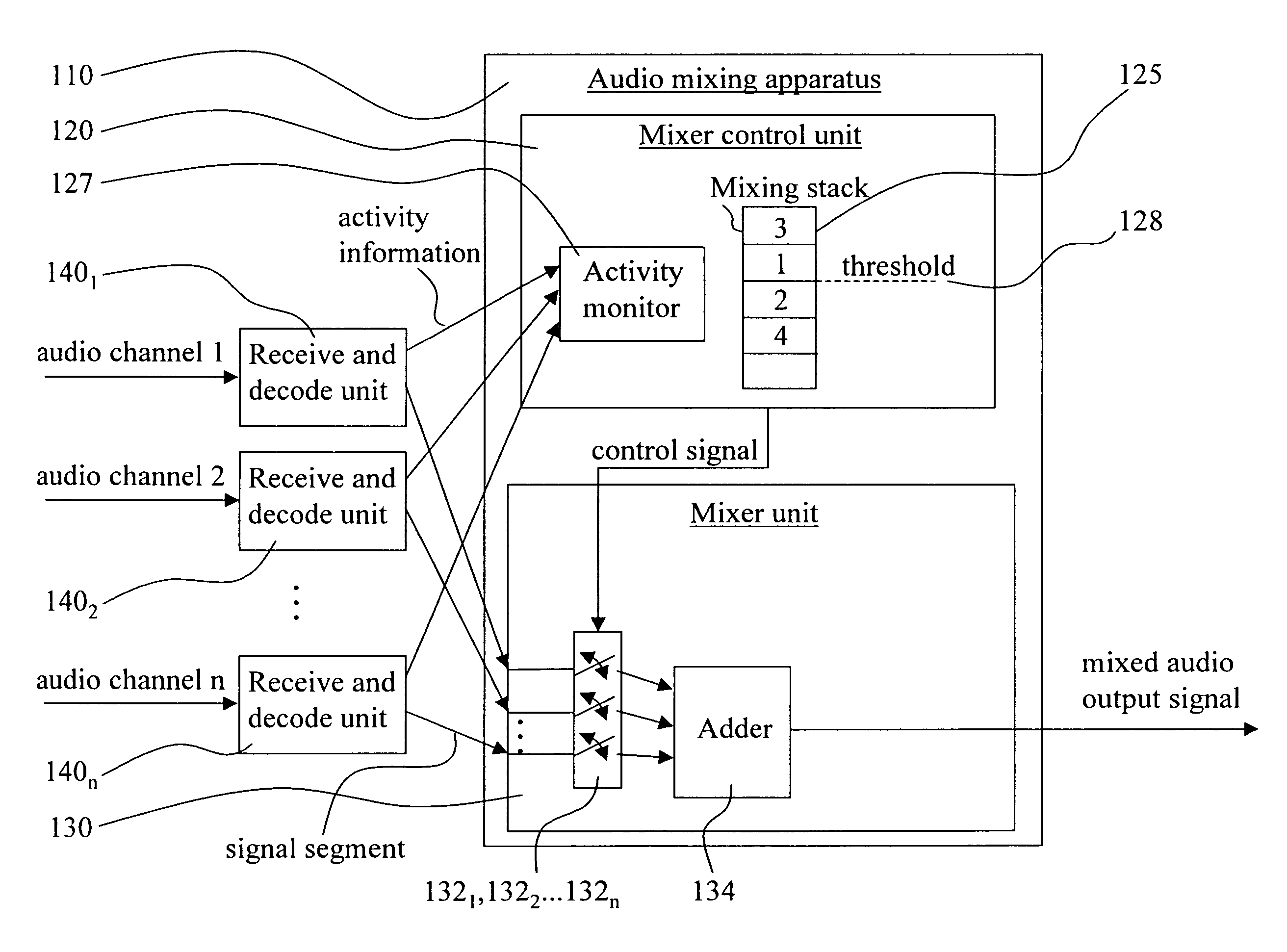
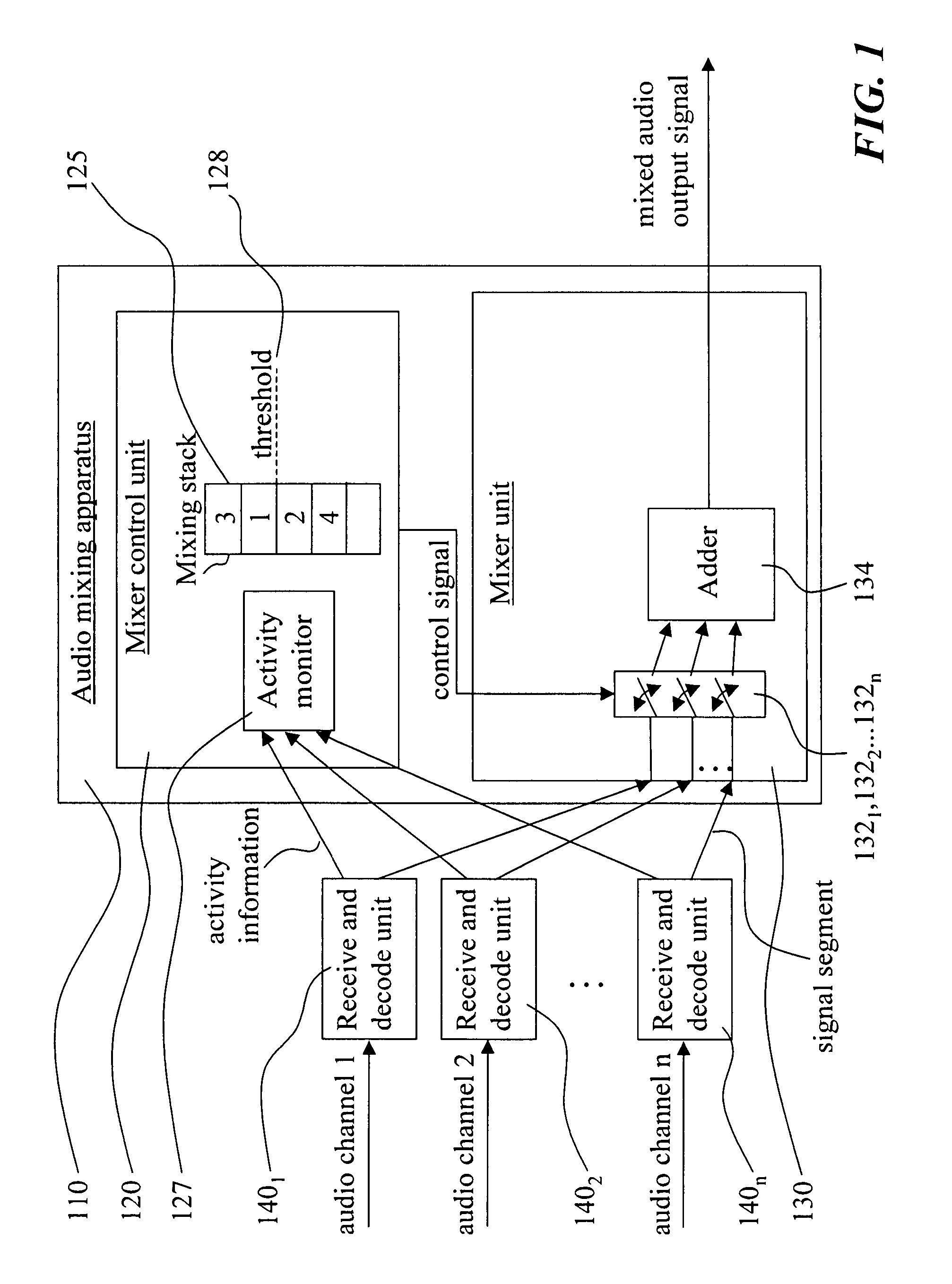
[0023]FIG. 1 schematically shows an exemplifying audio mixing apparatus 110 having a structure and operation in accordance with the invention.

[0024]The audio mixing apparatus 110 includes a mixer control unit 120 and a mixer unit130. The mixer control unit 120 includes, or is operably connected to, a mixing stack 125 and an activity monitor 127. The mixing stack includes a number of levels and each level is capable of storing a channel identifier. The mixing stack can also be regarded as a list with channel identifiers. The activity monitor is responsible for monitoring activity information received for all channels that potentially should be mixed by the mixing apparatus 110. The mixer control unit 120 is operably connected to the mixer unit 130 in order to be able to provide control information to the same. Connected to the audio mixing apparatus 110 is a set of receive and decode units 1401, 1402 . . . 140n which provide activity information to the mixer control unit 120 and sign...


PUM


Abstract

The invention relates to a method and an apparatus for mixing audio signals. The invention is based on the idea to base selection of what audio channels to mix on the dynamic behavior of the audio channels in terms of whether they are active or not, rather than basing the selection on quantative measures of the audio channels. According to the invention, a set of audio channels are arranged in a mixing stack and a mixed audio signal is produced from the topmost channels above a predetermined threshold level in the stack. Whenever a channel becomes active, it is placed at the top of the stack.

Description

[0001]This Nonprovisional application claims priority under 35 U.S.C.§119(e) on U.S. Provisional Application No(s). 60 / 799,683 filed on May 12, 2006 and under 35 U.S.C. §119(a) on European Application No(s). 06113826.9 filed on May 11, 2006, the entire contents of which are hereby incorporated by reference.TECHNICAL FIELD OF THE INVENTION[0002]The present invention relates to a method of mixing audio signals and an audio mixing apparatus designed to operate in accordance with such a method.TECHNICAL BACKGROUND AND PRIOR ART[0003]In an audio conferencing system, several participants are connected to a conference bridge. The conference bridge will handle admission control of participants, conference control functions etc. When an audio conference is ongoing, the conference bridge performs media processing in order to receive audio signals from the participants, mix the audio signals to a total signal that will be transmitted to the participants (with the exception that its own signal ...

Claims


Application Information

Patent Timeline
Patent Type & Authority Patents(United States)
IPC IPC(8): H04B1/00H04M3/42H04B1/20
CPCH04M3/56H04M3/563H04M3/568H04M3/569H04R3/005H04M2201/18
Inventor HAGEN, ROARENBOM, NIKLAS
Owner GOOGLE LLC
Learn More