
Active heating system for underwater diver

a technology of active heating and underwater environment, applied in the field of active heating system, can solve the problems of underwater environment not having a ready supply of oxygen, hands and feet of people typically getting cold first,

Inactive Publication Date: 2012-12-25
USA REPRESENTED BY THE SEC OF THE NAVY
View PDF26 Cites 6 Cited by
  • Summary
  • Abstract
  • Description
  • Claims
  • Application Information

AI Technical Summary

Benefits of technology

The technical effect of this patent is that it provides an improved method for producing flexible glass by melting the material at high temperatures and then rapidly cooling it down. This process results in better quality glass with fewer defects, making it easier to use in various applications such as electronics or optical devices.

Problems solved by technology

The patent text discusses the problem of cold hands and feet in cold environments and the use of chemical hand and foot warmers that contain iron particles that generate heat through a reaction with oxygen. However, these warmers are not suitable for underwater environments as they require air space and oxygen to work. The technical problem is how to provide a safe and effective solution for underwater divers to prevent their hands and feet from getting cold in cold environments.

Method used


Image

  • Active heating system for underwater diver
  • Active heating system for underwater diver
  • Active heating system for underwater diver

Examples


Embodiment Construction

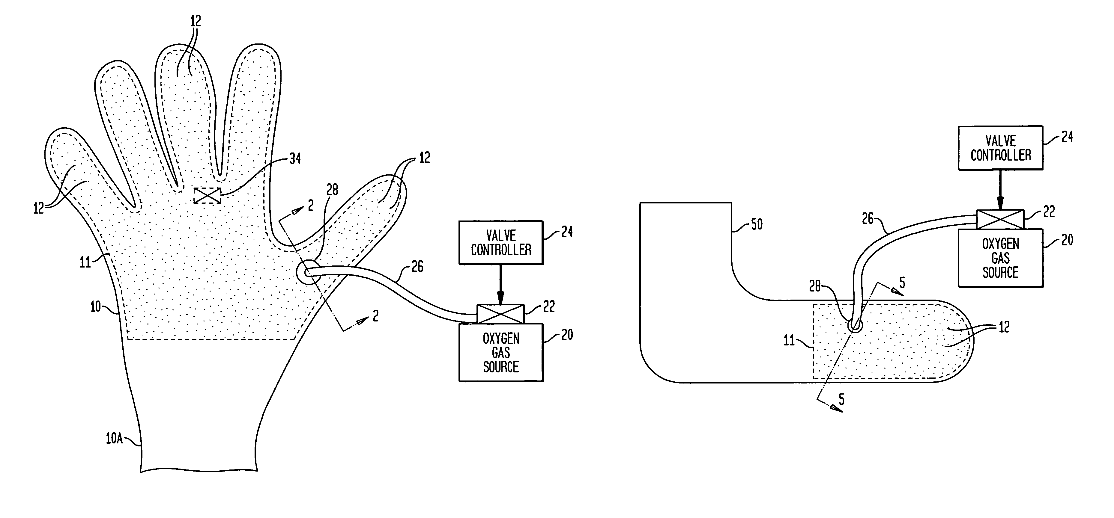
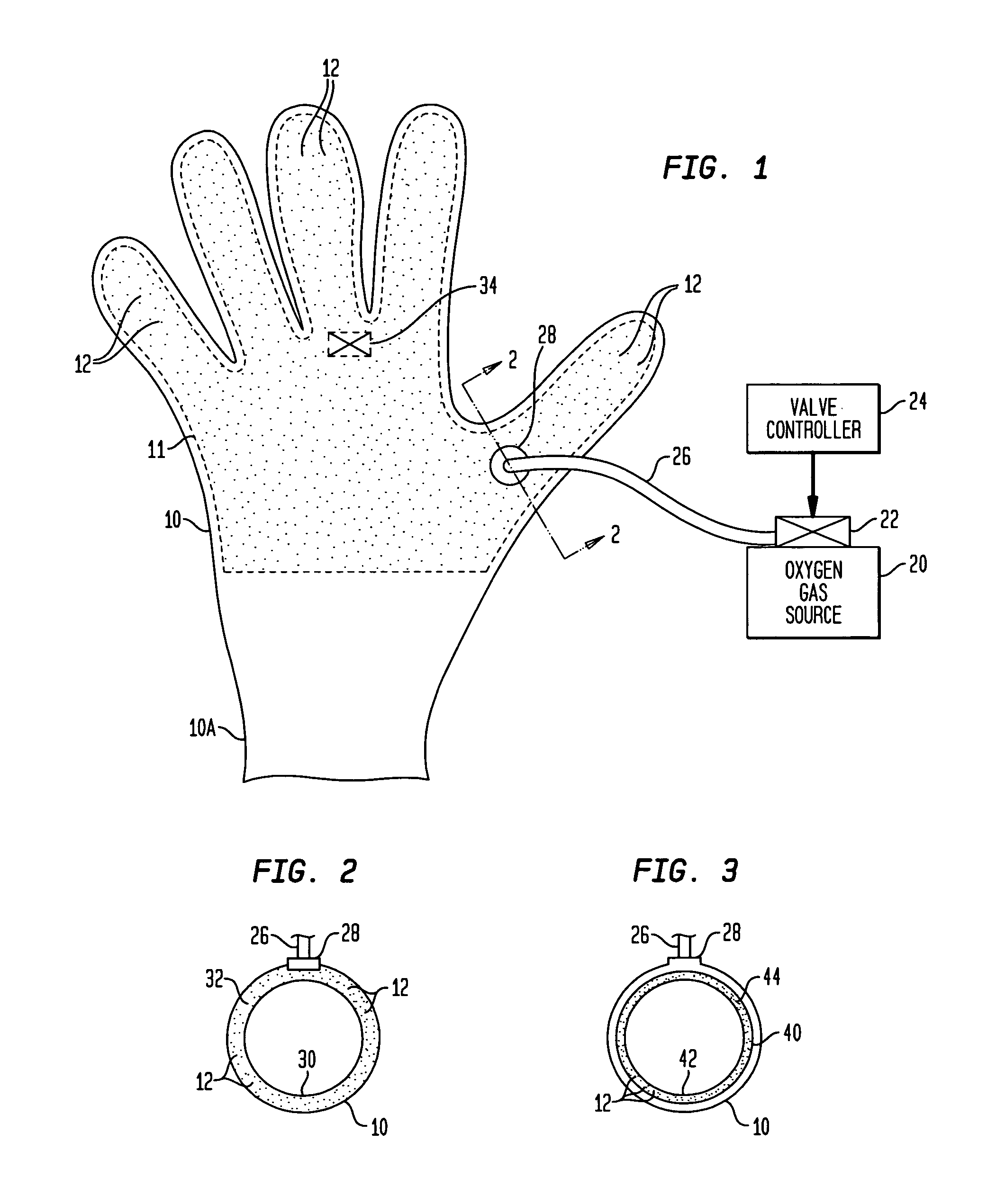
[0017]Referring now to the drawings and more particularly to FIG. 1, an active heating system for an underwater diver's glove 10 is shown. Diver's glove 10 is any conventional glove suitable for use in underwater diving applications. Typically, glove 10 is part of a diver's wetsuit or drysuit attire that is donned after a diver puts on main dive suit body (not shown). Glove 10 can be made from a variety of fluid-impermeable wetsuit or drysuit materials without departing from the scope of the present invention. Glove 10 terminates in a wrist seal 10A as is well known in the art.

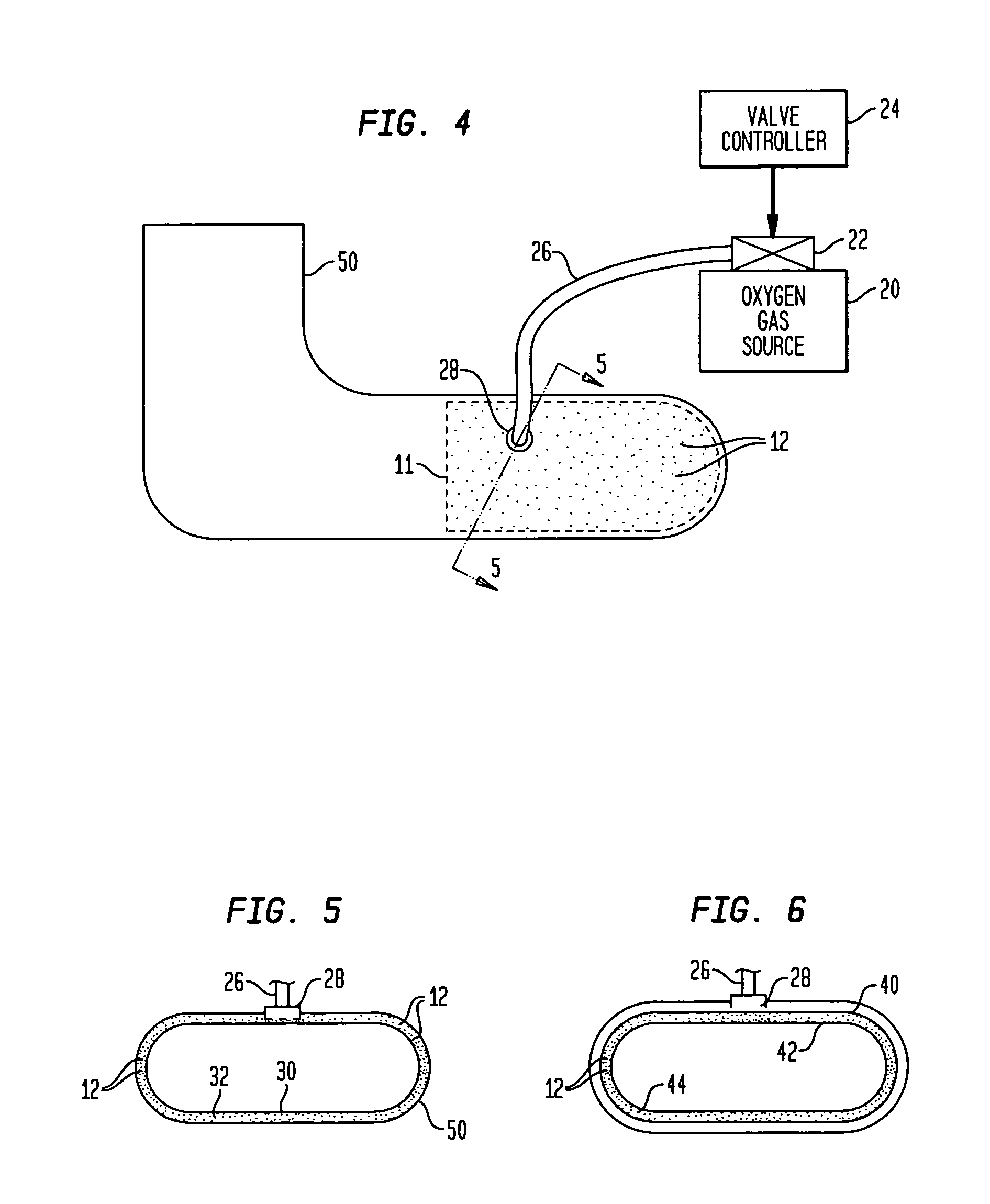
[0018]In general, glove 10 has one or more volumetric regions defined therein with material particles 12 disposed in each of the regions. For example, the illustrated embodiment depicts a contiguous region (defined by dashed lines 11) that includes the palm region and all five fingers. However, it is to be understood that other volumetric regions could be defined in glove 10 without departing from the scope of...


PUM


Abstract

An active heating system for an underwater diver uses material particles that can generate heat in an exothermic reaction in the presence of oxygen. The material particles are positioned at selected region(s) within an underwater diver's attire. A source of oxygen gas is coupled to the selected region(s).

Description


Claims


Application Information

Patent Timeline
Owner USA REPRESENTED BY THE SEC OF THE NAVY
Learn More