
Crystal growing systems and methods including a passive heater

a technology of crystal growth and passive heating, applied in the direction of crystal growth process, polycrystalline material growth, under a protective fluid, etc., can solve the problems of limiting the rate at which thermal energy may be supplied to the melt, relative low thermal conductivity,

Active Publication Date: 2016-01-28
CORNER STAR LTD
View PDF12 Cites 3 Cited by
  • Summary
  • Abstract
  • Description
  • Claims
  • Application Information

AI Technical Summary

Benefits of technology

The patent describes a system and method for growing crystal ingots from a melt using a crucible assembly and a secondary heating system. The crucible assembly includes a crucible and a weir for separating an outer melt zone from an inner melt zone. The secondary heating system includes an active heater and a passive heater, which transfers thermal radiation generated by the active heater to the outer melt zone using the passive heater. This method allows for precise control over the temperature and the distribution of thermal energy during the crystal growth process. The refinements of the patent include the use of a crucible assembly and a secondary heating system with a passive heater for supplying thermal energy to the outer melt zone, an active heater for generating thermal radiation, and a combination of both active and passive heaters. These technical features improve the quality and yield of crystal ingots and expand the range of crystalline materials that can be grown using this method.

Problems solved by technology

Crucibles typically have a relatively low thermal conductivity, which tends to limit the rate at which thermal energy may be supplied to the melt.
Limiting the rate at which thermal energy can be supplied to the melt may in turn limit the rate at which crystal ingots may be grown, thereby limiting the throughput of such devices.

Method used


Image

  • Crystal growing systems and methods including a passive heater
  • Crystal growing systems and methods including a passive heater
  • Crystal growing systems and methods including a passive heater

Examples


Embodiment Construction

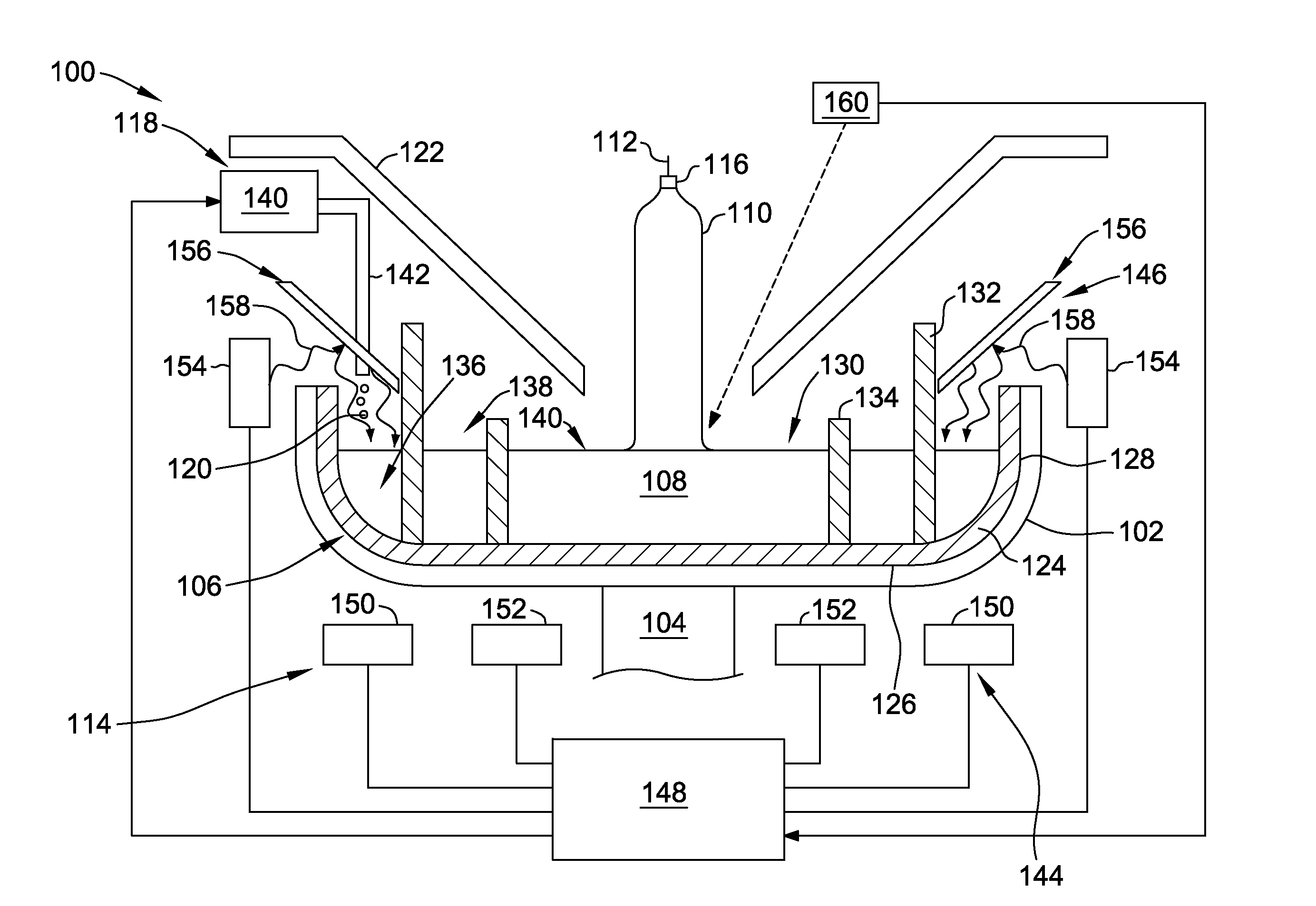
[0012]Referring to FIG. 1, a crystal growing system is shown schematically and is indicated generally at 100. The crystal growing system 100 is used to produce a single crystal ingot by a Czochralski method. As discussed herein, the system is described in relation to the continuous Czochralski method of producing single crystal ingots, though a batch process may be used. For example, the process may be used in a “recharge” CZ process.

[0013]The crystal growing system 100 includes a susceptor 102 supported by a rotatable shaft 104, a crucible assembly 106 that contains a silicon melt 108 from which an ingot 110 is being pulled by a puller 112, and a heating system 114 for supplying thermal energy to the system 100 and maintaining the melt 108. During the crystal pulling process, a seed crystal 116 is lowered by the puller 112 into the melt 108 and then slowly raised from the melt 108. As the seed crystal 116 is slowly raised from the melt 108, silicon atoms from the melt 108 align the...


PUM


Abstract

A system for growing a crystal ingot from a melt is provided. The system includes a crucible assembly, a first heater, a second heater, and a passive heater. The crucible assembly includes a crucible and a weir separating an outer melt zone of the melt from an inner melt zone of the melt. The first heater is configured to supply thermal energy to the melt by conduction through the crucible. The second heater is configured to generate thermal radiation. The passive heater is configured to supply thermal energy to the outer melt zone by transferring thermal radiation generated by the second heater to the outer melt zone.

Description

FIELD[0001]The field of the disclosure relates generally to systems and methods for producing ingots of semiconductor or solar material from a melt and, more particularly, to systems and methods for the transfer of heat to the melt.BACKGROUND[0002]In the production of silicon crystals grown by the continuous Czochralski (CCZ) method, polycrystalline silicon is first melted within a crucible, such as a quartz crucible, of a crystal pulling device to form a silicon melt. The puller then lowers a seed crystal into the melt and slowly raises the seed crystal out of the melt. As the seed crystal is grown from the melt, solid polysilicon is added to the melt to replenish the polysilicon that is incorporated into the growing crystal. The addition of polysilicon to the melt reduces the temperature of the melt where the solid polysilicon is added. As a result, additional heat is needed to melt the solid polysilicon, and maintain the melt in a liquid state.[0003]Known crystal pulling devices ...

Claims


Application Information

Patent Timeline
IPC IPC(8): C30B15/14C30B15/00C30B15/12C30B29/06
CPCC30B15/14C30B29/06C30B15/12C30B15/002Y10T117/1052Y10T117/1068C30B15/206
Inventor SWAMINATHAN, TIRUMANI
Owner CORNER STAR LTD
Learn More