Methods and devices for utilizing thermal energy to bond, stake and/or remove implants

a technology of thermal energy and implants, applied in the field of fixation or fastening of tissues and implants, can solve the problems of fractured bones, one-solution-fixing-all devices not available, and large amount of ligaments being torn away from bones, etc., and achieves the effect of simple mechanical retention of one part relative to another and short cycle tim

Active Publication Date: 2009-01-22
P TECH
View PDF100 Cites 266 Cited by
  • Summary
  • Abstract
  • Description
  • Claims
  • Application Information

AI Technical Summary

Benefits of technology

[0338]Although the above-discussion emphasizes bonding or welding, the present invention also contemplates staking in most situations as an alternative or supplement. Staking generally involves the mechanical interlock of dissimilar materials. Staking is the process of melting and reforming a piece, such as a stud, to mechanically lock a material in place. It provides an alternative to bonding when two parts to be joined are made of dissimilar materials that cannot be bonded, or simple mechanical retention of one part relative to another is adequate.
[0339]The advant...

Problems solved by technology

For example, trauma to the rotator cuff usually results in a portion, if not all, of the ligament being torn away from bone.
Currently, a one-solution-fixes-all device is not available to repair fractured bones.
However, one drawback with plates and screws is that with the dynamic loading placed on the plate, loosening of the screws and loss of stored compression can result.
One problem associated with the use of today's intramedullary rods is that it is often difficult to treat fractures at the end of the long bone.
However, the number and posi...

Method used


Image

  • Methods and devices for utilizing thermal energy to bond, stake and/or remove implants
  • Methods and devices for utilizing thermal energy to bond, stake and/or remove implants
  • Methods and devices for utilizing thermal energy to bond, stake and/or remove implants

Examples


Embodiment Construction

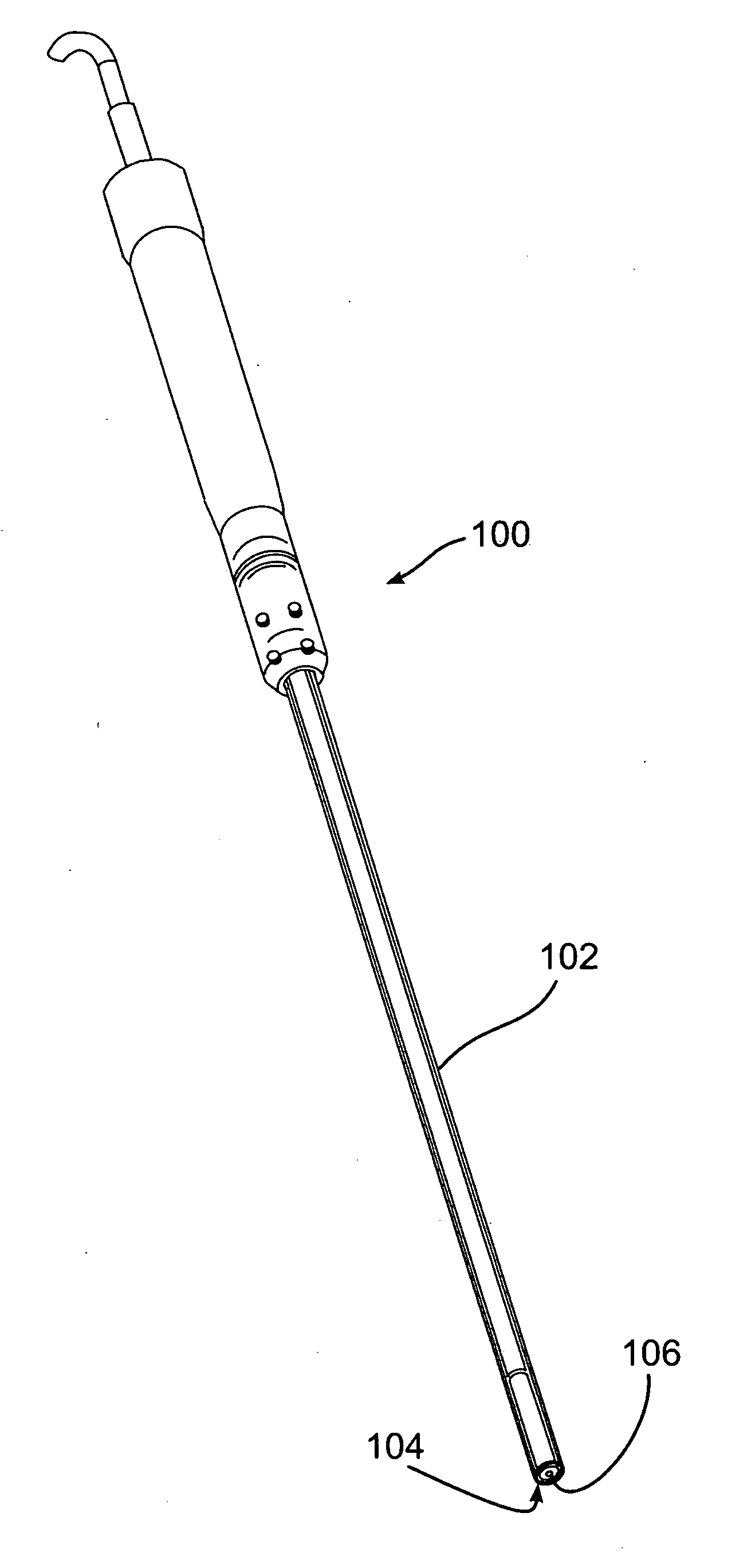
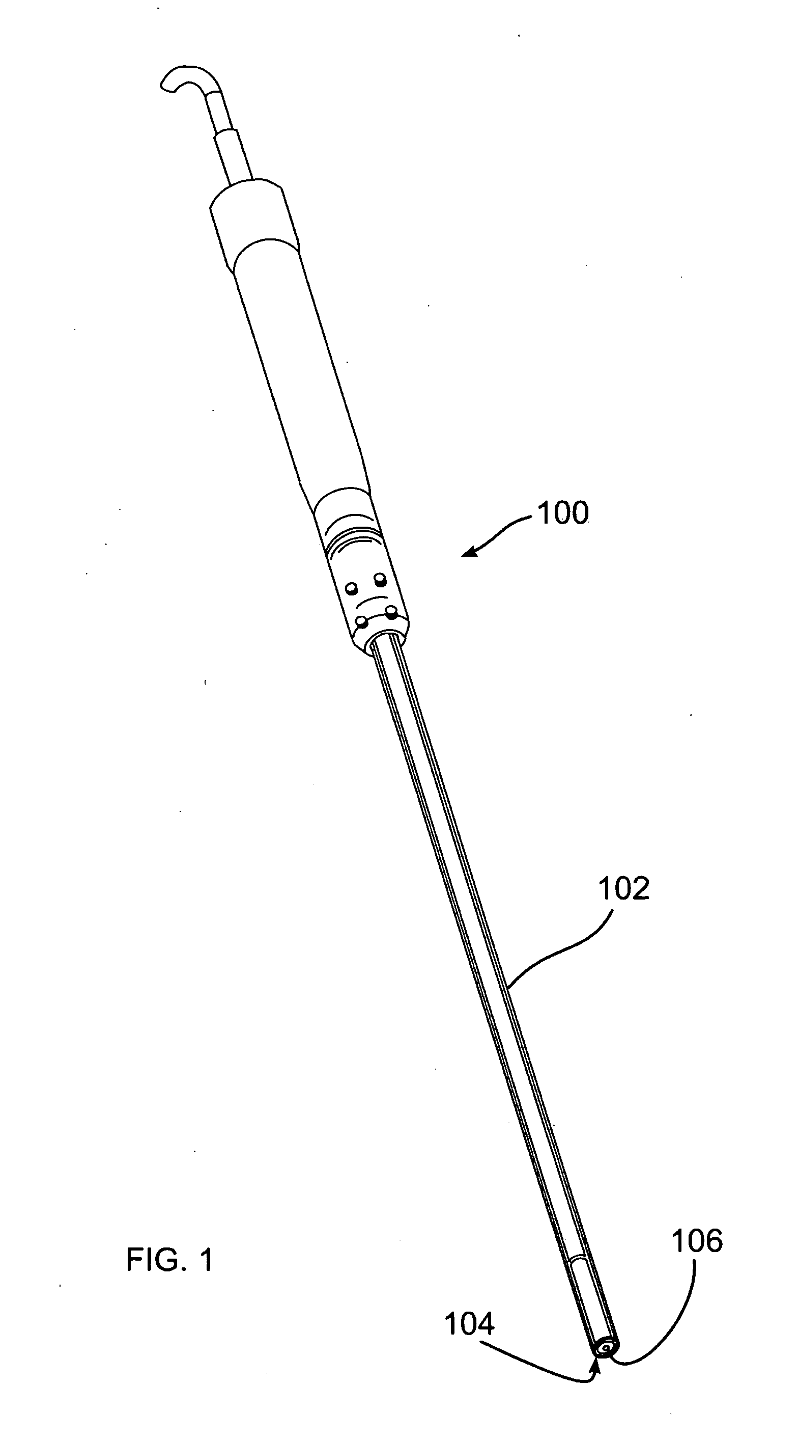
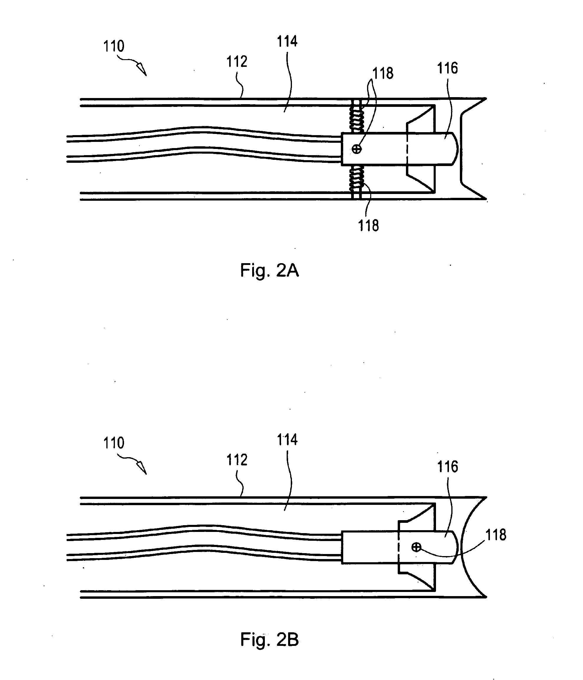
[0387]As detailed below, the invention provides for stabilization of implants or body structures, including fastening of a chain of implants. The invention additionally relates to removing implants fastened with bondable materials using vibratory energy, including for example ultrasonic energy. The invention further provides for locking similar or dissimilar materials together in the body by providing a surface between elements that is roughened or porous, or which has one or more cavities or projections upon which melted material may form and lock to once cooled. Additionally disclosed are devices for generating and controlling vibratory delivery, and mixing materials using vibratory energy.

[0388]The methods and devices disclosed herein may be used in conjunction with any surgical procedure of the body. The fastening and repair of tissue or an implant may be performed in connection with surgery of a joint, bone, muscle, ligament, tendon, cartilage, capsule, organ, skin, nerve, vess...


PUM

PropertyMeasurementUnit
Temperatureaaaaaaaaaa
Angleaaaaaaaaaa
Shapeaaaaaaaaaa

Abstract

A fastener including material meltable at a temperature not likely to produce substantial tissue necrosis of neighboring body tissue, or “bondable material”, is caused to soften or melt by the application of vibratory energy, advantageously including ultrasonic vibratory energy. Vibratory energy is applied using a horn applied to the fastener, and tuned to generate vibratory motion proximate the horn, or at a point distal to the horn, for example at a point along the fastener body, or at the end of the fastener. Melted or softened material of the fastener bonds to a contacting surface, which may be body tissue or another implant. The contacting surface may also include bondable material, softenable or meltable through vibratory energy derived from contact with the fastener. To improve a bond, particularly where dissimilar materials are to be bonded, one or more contacting surfaces is provided with a roughened or porous surface, or a surface including one or more cavities or projections into or onto which softened or melted bondable material may form, bonding once the bondable material has cooled.

Description

CROSS REFERENCE TO RELATED APPLICATIONS[0001]This application is a non-provisional patent application claiming benefit under 35 U.S.C. §119(e) of U.S. Provisional Application No. 60 / 968,969, filed Aug. 30, 2007, the entire contents of which are hereby expressly incorporated by reference into this disclosure as if set forth fully herein. This application is also a continuation-in-part application of: U.S. patent application Ser. No. 11 / 416,618 filed May 3, 2006; U.S. patent application Ser. No. 11 / 689,670, filed Mar. 22, 2007; and U.S. patent application Ser. No. 11 / 671,556, filed Feb. 6, 2007. The '556 application claimed the benefit of the following U.S. Provisional Applications: 60 / 765,857 filed Feb. 7, 2006; 60 / 784,186 filed Mar. 21, 2006; and 60 / 810,080 filed Jun. 1, 2006. The entire contents of each of the aforementioned applications are hereby expressly incorporated by reference into this disclosure as if set forth fully herein.FIELD OF THE INVENTION[0002]The invention relates...

Claims


Application Information

Patent Timeline
IPC IPC(8): A61B17/08
CPCA61B17/0401A61B17/0487A61B17/11A61B17/1128A61B17/1146A61B17/320068A61B17/68A61B17/7058A61B17/7059A61B17/7098A61B17/7225A61B17/7233A61B17/7258A61B17/80A61B17/866A61B17/8685A61B17/8802A61B17/8822A61B17/8872A61B2017/005A61B2017/0409A61B2017/044A61B2017/1107A61F2/0811A61F2/30A61F2/30721A61F2/30756A61F2/3094A61F2/32A61F2/34A61F2/36A61F2/3603A61F2/38A61F2/3804A61F2/3859A61F2/389A61F2/40A61F2/4081A61F2/4202A61F2/44A61F2/4455A61F2/46A61F2/468A61F2/82A61F2/90A61F2002/067A61F2002/2817A61F2002/30062A61F2002/30065A61F2002/30067A61F2002/30133A61F2002/30451A61F2002/30576A61F2002/30604A61F2002/30677A61F2002/3068A61F2002/30785A61F2002/30787A61F2002/30878A61F2002/30892A61F2002/30894A61F2002/30971A61F2002/30973A61F2002/3401A61F2002/3403A61F2002/444A61F2002/4619A61F2002/4683A61F2002/828A61F2210/0004A61F2210/0071A61F2220/0058A61F2230/0015A61F2250/0068A61F2310/00011A61F2310/00365A61F2310/00383A61F2310/00952A61F2220/0008A61N7/00A61B2017/00955A61B8/429A61B2090/065A61N2007/0013
Inventor BONUTTI, PETER M.CREMENS, MATTHEW J.BEYERS, JUSTIN E.
Owner P TECH
Why Eureka
Try Eureka