
Aiming system for weapon

a technology of aiming system and optical sight, applied in the field of optical sight, can solve the problems of conventional optical sight that does not adjust the position of the reticle relative to the optical sight based on target parameters (i, environmental conditions)

Active Publication Date: 2012-12-25
TRIJICON INC
View PDF123 Cites 67 Cited by
  • Summary
  • Abstract
  • Description
  • Claims
  • Application Information

AI Technical Summary

Benefits of technology

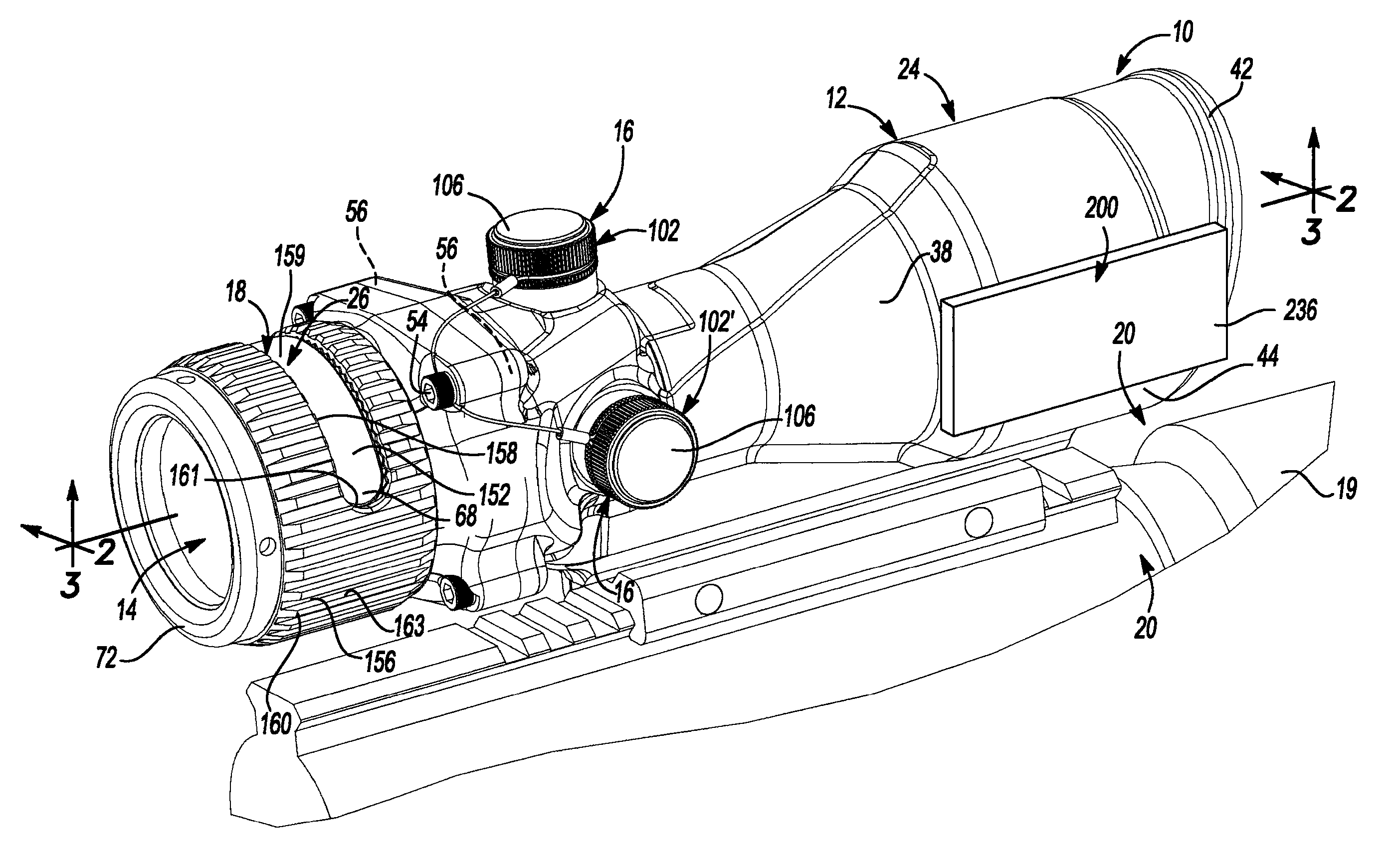
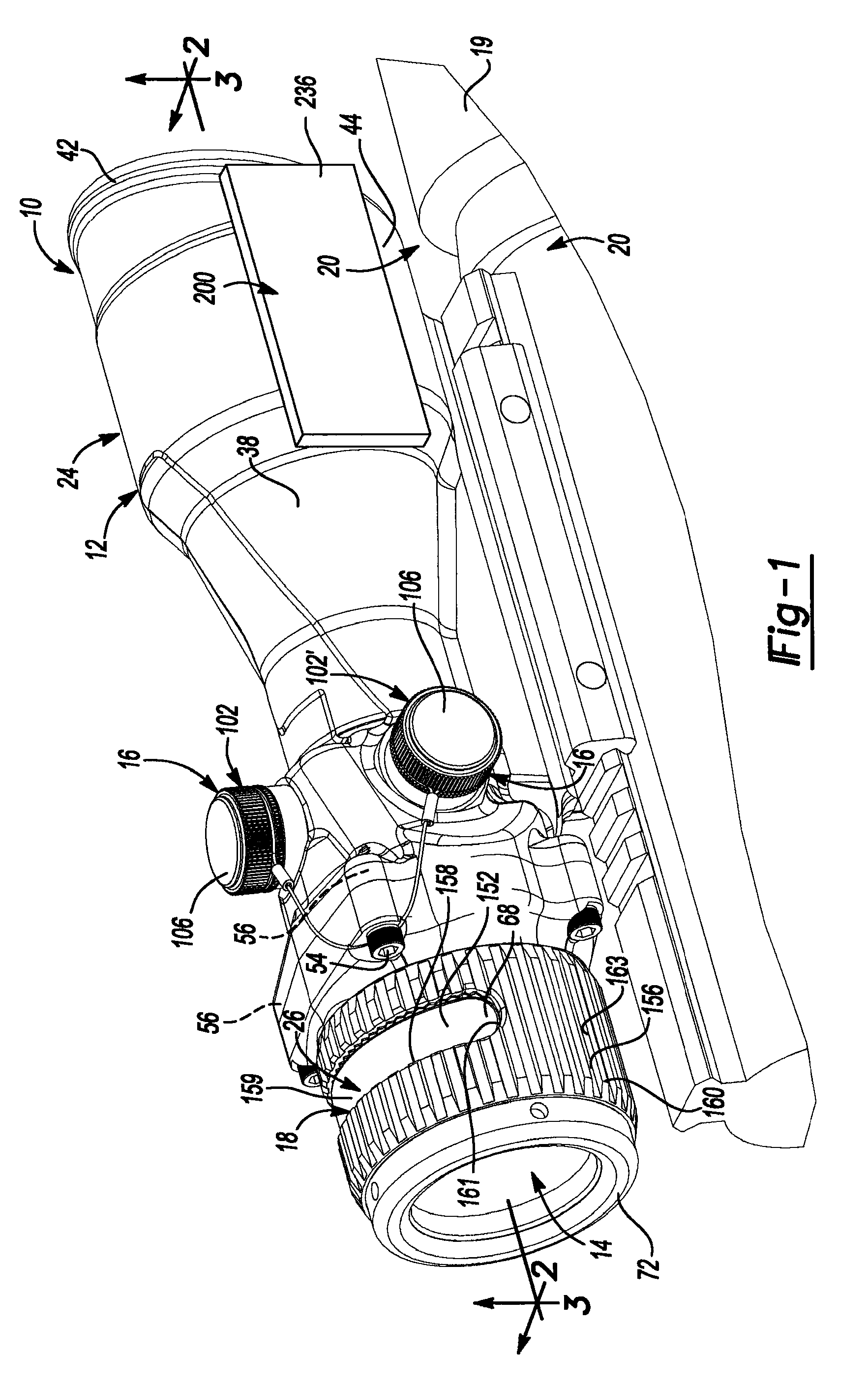
[0009]A method is provided and may include aligning a weapon with a desired target, energizing an aiming system associated with the weapon, determining a range to the target, generating by a processor a number of simulated bullet trajectories, and generating by the processor a number of simulated bullet impact locations. The method may also include generating by the processor the simulated bullet trajectories and the simulated bullet impact locations until an error between the simulated bullet impact location and the target is within a predetermined range. A corrected-aiming point may be generated if the error is within the predetermined range to aid a shooter in adjusting a position of the weapon to allow a projectile fired from the weapon to contact the target at a desired location.
[0010]In another configuration, a method is provided and may include aligning a weapon with a static target, energizing an aiming system associated with the weapon, determining a range to the static target, and generating by a processor a static corrected-aiming point to aid a shooter in adjusting a position of the weapon to allow a projectile fired from the weapon to contact the static target at a desired location. The method may also include detecting movement of the target and generating by the processor a moving corrected-aiming point based on the static corrected-aiming point to aid the shooter in adjusting a position of the weapon to allow a projective fired from the weapon to contact the moving target at a desired location.
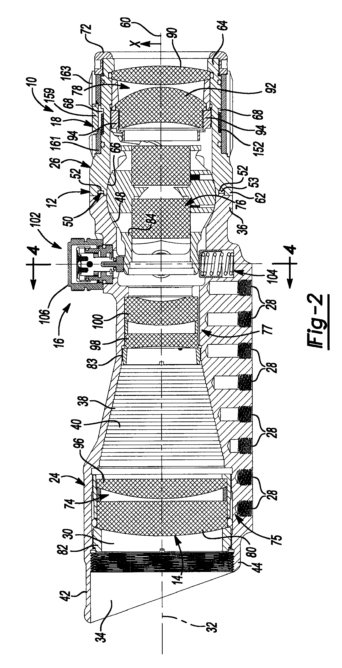
[0011]In another configuration, an aiming system for use with a weapon is provided and may include a housing, an optics train disposed within the housing and including an optical element having a reticle, and a laser-range finder supported by the housing adjacent to the optics train. The aiming system may also include a linkage attached to the laser-range finder and supported by the housing by a grommet that permits rotation of the linkage relative to the housing and permits pivoting of the linkage relative to the housing. The linkage may adjust a position of the laser-range finder in a first direction in response to movement of the optical element in the first direction by rotating about the grommet and may adjust a position of the laser-range finder in a second direction in response to movement of the optical element in the second direction by pivoting at the grommet.

Problems solved by technology

While conventional optical sights adequately magnify an image and properly align the magnified image with a barrel of a firearm, conventional optical sights do not adjust a position of a reticle relative to the optical sight based on target parameters (i.e., location, movement, etc.), environmental conditions, or otherwise.
Rather, conventional optical sights are typically limited to a fixed-position reticle that a user must align relative to a target, thereby relying solely on the skill of the user in properly aligning the optical sight and firearm relative to the target.

Method used


Image

  • Aiming system for weapon
  • Aiming system for weapon
  • Aiming system for weapon

Examples


Embodiment Construction

[0045]Example embodiments will now be described more fully with reference to the accompanying drawings.

[0046]Example embodiments are provided so that this disclosure will be thorough, and will fully convey the scope to those who are skilled in the art. Numerous specific details are set forth such as examples of specific components, devices, and methods, to provide a thorough understanding of embodiments of the present disclosure. It will be apparent to those skilled in the art that specific details need not be employed, that example embodiments may be embodied in many different forms and that neither should be construed to limit the scope of the disclosure. In some example embodiments, well-known processes, well-known device structures, and well-known technologies are not described in detail.

[0047]The terminology used herein is for the purpose of describing particular example embodiments only and is not intended to be limiting. As used herein, the singular forms “a,”“an” and “the” m...


PUM


Abstract

An aiming system for use with a weapon is provided and may include a processor, at least one sensor in communication with the processor, and a memory in communication with the processor. The aiming system may also include a display in communication with the processor that displays a corrected-aiming point based on at least one simulated bullet trajectory and at least one simulated bullet impact location determined by the processor.

Description

CROSS-REFERENCE TO RELATED APPLICATIONS[0001]This application claims the benefit of U.S. Provisional Application No. 61 / 360,008, filed on Jun. 30, 2010. The entire disclosure of the above application is incorporated herein by reference.FIELD[0002]The present disclosure relates to optical sights and more particularly to an aiming system for use with an optical sight.BACKGROUND[0003]This section provides background information related to the present disclosure which is not necessarily prior art.[0004]Optical sights are conventionally used with weapons such as guns, rifles, and other firearms to allow a user to more clearly see a target. Conventional optical sights include a series of lenses that magnify an image and provide a reticle or aiming point that allows a user to align a magnified target relative to a barrel of the firearm. Proper alignment of the optical sight with the barrel of the firearm allows the user to align the barrel of the firearm and, thus, a projectile fired there...

Claims


Application Information

Patent Timeline
IPC IPC(8): G06F19/00G06G7/80
CPCF41G1/38F41G1/473F41G3/142F41G3/08F41G3/06
Inventor HORVATH, ANTHONYADKINS, AARONWILLARD, RICHARDSTOLTZ, PAUL
Owner TRIJICON INC
Learn More