
Systems and methods for data recovery using enhanced sync mark location

a technology of enhanced sync mark and location, applied in the field of systems and methods for identifying reproducible locations on storage media, can solve the problems of data loss, circuitry and time costs of search approaches,

Active Publication Date: 2013-01-01
AVAGO TECH INT SALES PTE LTD
View PDF42 Cites 12 Cited by
  • Summary
  • Abstract
  • Description
  • Claims
  • Application Information

AI Technical Summary

Problems solved by technology

Such search approaches are often costly in terms of circuitry and time.
Further, in some cases, the search approaches are not capable of identifying the data sync mark resulting in the loss of data.

Method used


Image

  • Systems and methods for data recovery using enhanced sync mark location
  • Systems and methods for data recovery using enhanced sync mark location
  • Systems and methods for data recovery using enhanced sync mark location

Examples


Embodiment Construction

[0023]The present inventions are related to systems and methods for identifying a reproducible location on a storage medium, and more particularly to systems and methods for identifying a reproducible location on a storage medium based on a waveform correlation.

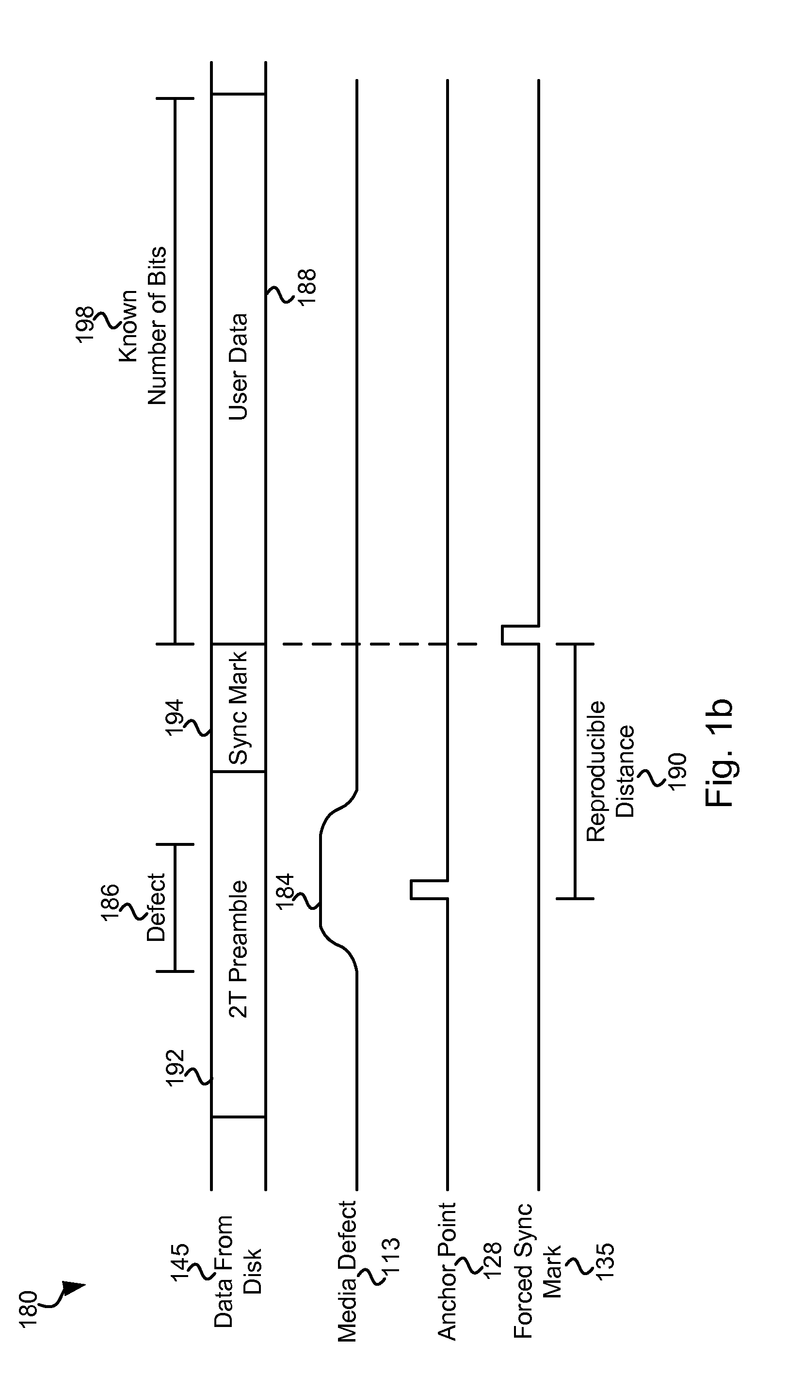
[0024]Various embodiments of the present invention provide forced data sync marks that may be used in place of original data sync marks that cannot be detected on a storage medium due to a media defect on the storage medium or some other anomaly. In one particular case, the forced data sync mark is located a defined distance from an identified waveform occurring within a window of interest. As media defects do not move and generally result in a reproducible waveform, albeit not a waveform corresponding to data written near the region of the media defect, the location of the waveform is reproducible. Because the location of the waveform is reproducible and the forced data sync mark is located relative to the waveform, the forc...


PUM

PropertyMeasurementUnit
threshold comparisonaaaaaaaaaa
thresholdaaaaaaaaaa
threshold valueaaaaaaaaaa

Abstract

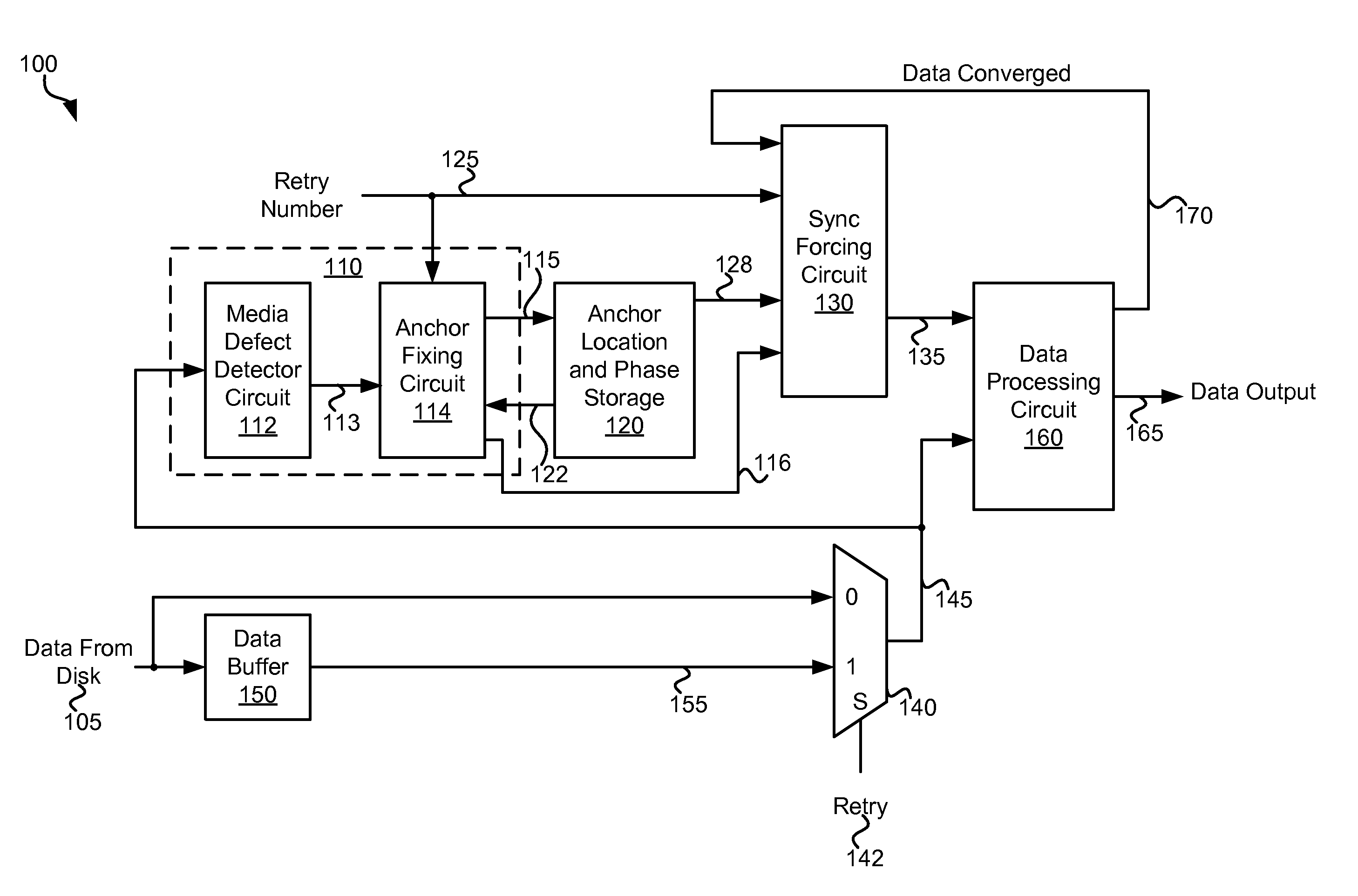
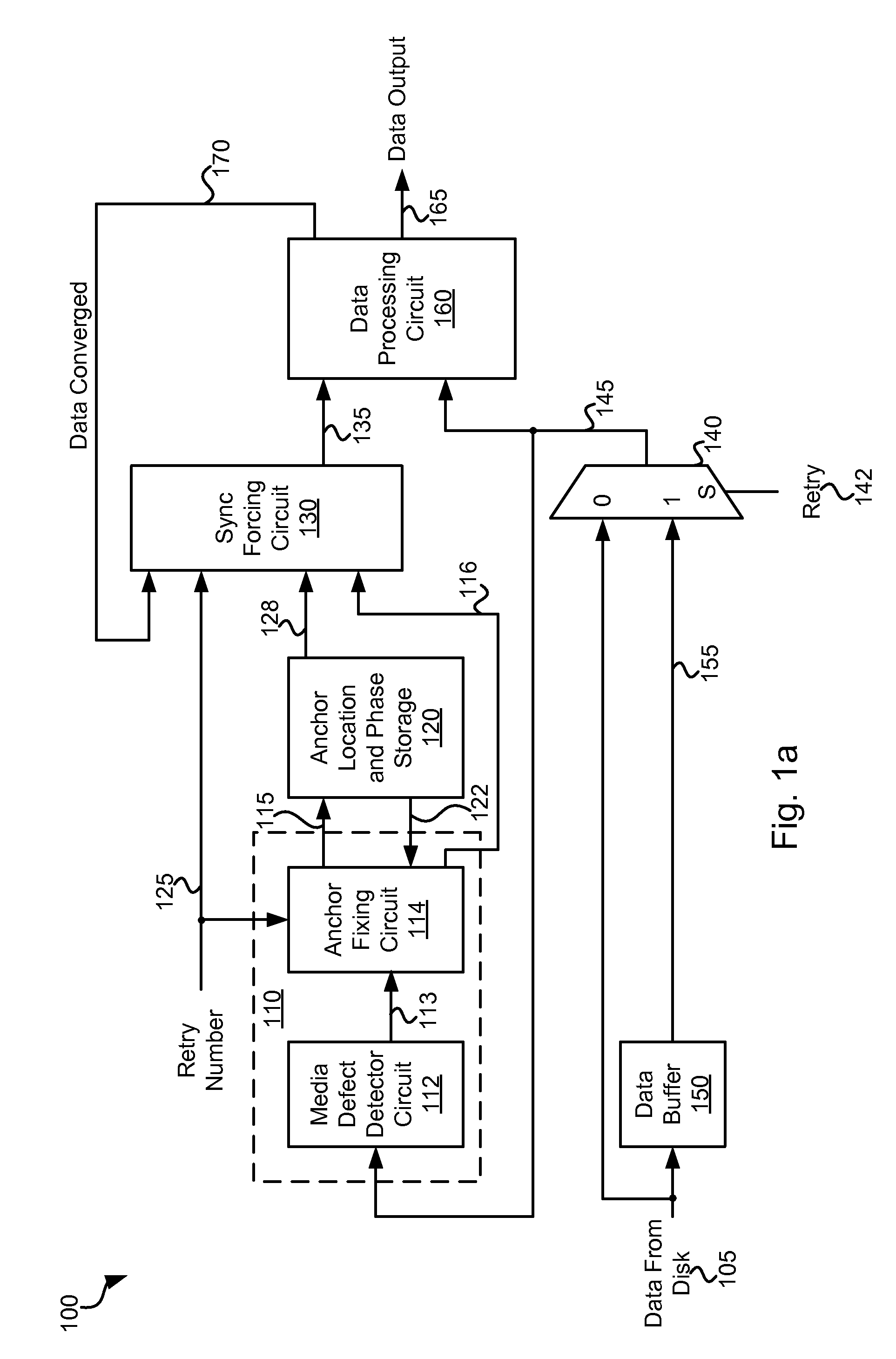
Various embodiments of the present invention provide systems and methods for identifying a reproducible location on a storage medium. As an example, a circuit is discussed that includes a data storage circuit, a pattern comparison circuit, and a threshold comparison circuit. The data storage circuit is operable to store a first set of data samples corresponding to a region of interest. The pattern comparison circuit is operable to compare a subset of the first set of data samples with a subset of a second set of data samples corresponding to the region of interest. The pattern comparison circuit is operable to yield a match value corresponding to a degree of similarity between the first set of data samples with the subset of a second set of data samples. The threshold comparison circuit is operable to indicate an anchor point based at least in part on the magnitude of the match value relative to a threshold value.

Description

CROSS REFERENCE TO RELATED APPLICATIONS[0001]The present application is a continuation in part of U.S. patent application Ser. No. 12 / 712,136 entitled “Systems and Methods for Data Recovery” and filed by Mathew et al. on Feb. 24, 2010. The entirety of the aforementioned reference is incorporated herein by reference for all purposes.BACKGROUND OF THE INVENTION[0002]The present inventions are related to systems and methods for identifying a reproducible location on a storage medium, and more particularly to systems and methods for identifying a reproducible location on a storage medium based on a waveform correlation.[0003]A hard disk typically includes a number of user data regions that are preceded by synchronization information including a preamble and a data sync pattern. The preamble is used to synchronize phase and frequency during an asynchronous read, and the data sync pattern is used to define the starting point of a series of user data. In operation, a circuit searches for t...

Claims


Application Information

Patent Timeline
Patent Type & Authority Patents(United States)
IPC IPC(8): G11B5/09
CPCG11B5/59616G11B20/1217G11B20/1403H03M13/33G11B2020/1287G11B2020/1294G11B2020/1476G11B2020/185
Inventor XIA, HAITAOYANG, SHAOHUAMATHEW, GEORGE
Owner AVAGO TECH INT SALES PTE LTD
Learn More