
Optical pickup device

a pickup device and optical technology, applied in the field of optical pickup devices, can solve the problem of not having a low-cost optical pickup device, and achieve the effect of low cost and spa

Inactive Publication Date: 2013-01-15
FUNAI ELECTRIC CO LTD +1
View PDF11 Cites 0 Cited by
  • Summary
  • Abstract
  • Description
  • Claims
  • Application Information

AI Technical Summary

Benefits of technology

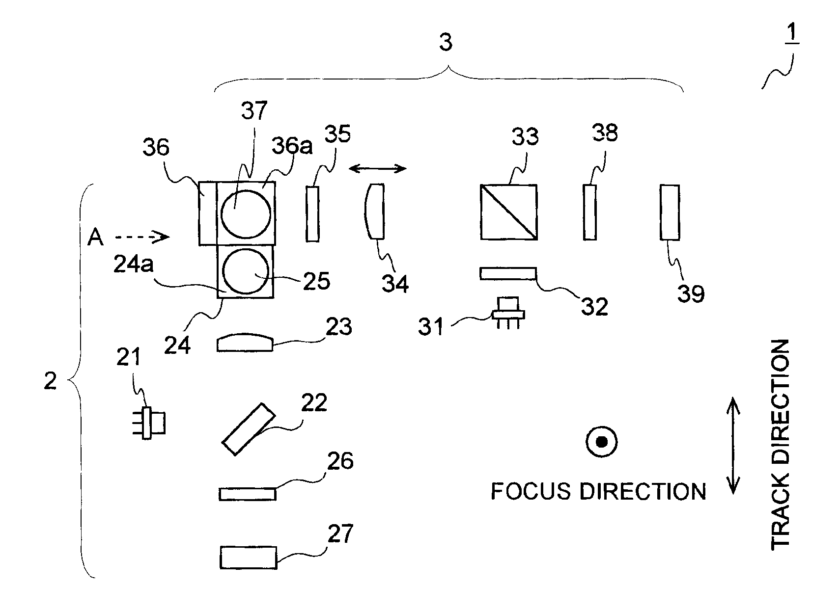
[0013]To overcome the foregoing problem, the present invention has an object to provide an optical pickup device which has two separate optical systems and with which it is possible to minimize, at a low cost, the space between objective lenses included in the optical systems.
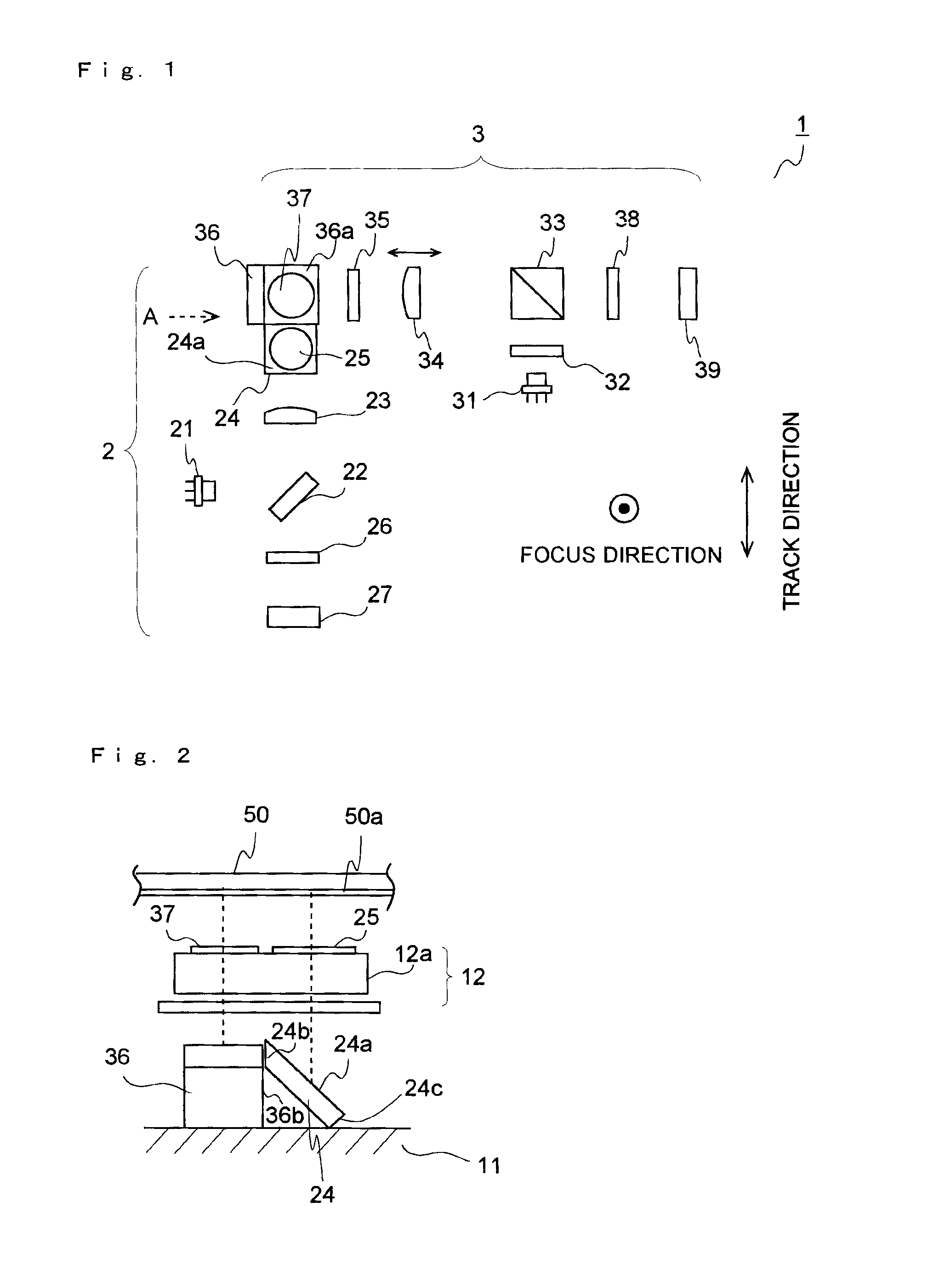
[0015]With the optical pickup device configured as described above, it is possible to simplify the shape of the first mirror member and the second mirror member and arrange the reflective surfaces of these two mirror members close to each other. Thus, it is possible to reduce the cost necessary to work the mirror members and thus minimize, at a low cost, the space between the objective lenses included in the optical systems.
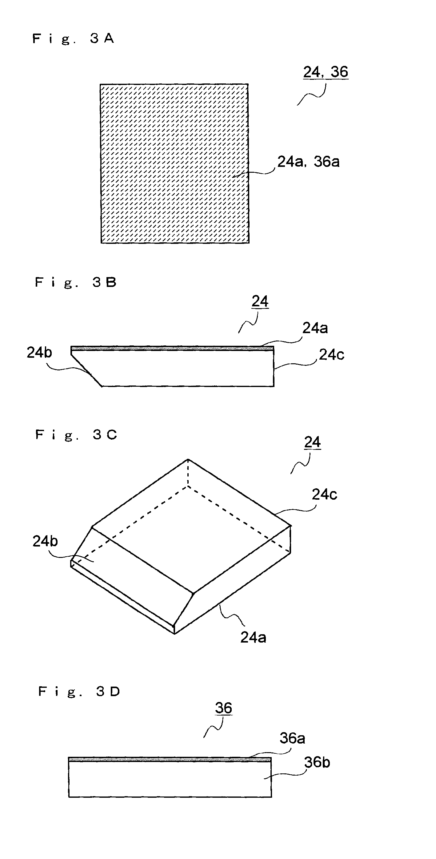
[0016]In the optical pickup device configured as described above, the first mirror member and the second mirror member may be a plate-shaped member that is substantially rectangular as seen from a reflective surface, and, in at least one of the first mirror member and the second mirror member, a cut surface may be formed by cutting a side surface of the plate-shaped member obliquely with respect to the reflective surface. This type of shape of the mirror member can be obtained by dicing, and thus it is easy to reduce the cost.
[0017]Preferably, in the optical pickup device configured as described above, in at least one of the first optical system and the second optical system, a plate-shaped light splitter is provided, and the light splitter guides part of the light from the light source to the optical disc and guides part of the return light from the optical disc to the light receiving element. This type of plate-shaped light splitter can be formed with a half mirror or a plate-shaped polarization beam splitter, and thus it is easy to reduce the cost of the optical pickup device.
[0020]As described above, according to the present invention, in the optical pickup device having the two separate optical systems, it is possible to minimize, at a low cost, the space between the objective lenses included in the optical systems.

Problems solved by technology

Conventionally, there are few examples of development with consideration given to this point, and furthermore, there are no optical pickup devices in which this is achieved at a low cost.

Method used


Image

  • Optical pickup device
  • Optical pickup device
  • Optical pickup device

Examples


Embodiment Construction

[0033]An embodiment of an optical pickup device of the present invention will be described below in detail with reference to the accompanying drawings. Before that, in order for the present invention to be easily understood, an optical pickup device (previously developed optical pickup device) that is previously developed by the applicant of the present invention will be introduced so that problems of the previously developed optical pickup device are made clear.

[0034](The Optical Pickup Device Previously Developed by the Applicant of the Present Invention)

[0035]FIG. 5 is a schematic plan view showing the configuration of the optical systems of the optical pickup device that is previously developed by the applicant of the present invention. This optical pickup device 100 includes two separate optical systems 101 and 102. The optical system 101 is referred to as the first optical system; the optical system 102 is referred to as the second optical system.

[0036]The first optical system...


PUM

PropertyMeasurementUnit
wavelength bandaaaaaaaaaa

Abstract

An optical pickup device includes a first optical system and a second optical system. The first optical system and the second optical system each include a mirror member that reflects light from a light source to change a direction of propagation of the light to a direction substantially perpendicular to the information storage surface of an optical disc. The first optical system and the second optical system are arranged such that a direction in which light from a first light source enters a first mirror member is substantially perpendicular to a direction in which light from a second light source enters a second mirror member.

Description

[0001]This application is based on Japanese Patent Application No. 2009-052885 filed on Mar. 6, 2009, the contents of which are hereby incorporated by reference.BACKGROUND OF THE INVENTION[0002]1. Field of the Invention[0003]The present invention relates to an optical pickup device and more particularly to the configuration of an optical pickup device having two separate optical systems that are selectively used according to the type of optical disc.[0004]2. Description of Related Art[0005]Conventionally, optical pickup devices are used to read information on an optical disc and write information on the optical disc. There are a plurality of types of optical discs such as a compact disc (CD), a digital versatile disc (DVD) and a blue-ray disc (BD). Thus, for convenience and the like, among conventional optical pickup devices, there are some optical pickup devices that can be compatible with a plurality of types of optical discs.[0006]Among the optical pickup devices compatible with ...

Claims


Application Information

Patent Timeline
Patent Type & Authority Patents(United States)
IPC IPC(8): G11B7/00
CPCG11B7/1275G11B7/1362G11B7/22G11B2007/0006
Inventor TANABE, NORITAKAMATSUBARA, DAISUKENAKAI, KENYA
Owner FUNAI ELECTRIC CO LTD
Learn More