Apparatus and methods for the placement of badges, ribbons and/or other items

a technology for placing badges and ribbons, applied in the field of methods and equipment for locating or placing items on carriers, can solve the problems of difficulty in precisely positioning, difficulty in locating items,

Active Publication Date: 2013-01-29
VANGUARD IND EAST INC
View PDF34 Cites 4 Cited by
  • Summary
  • Abstract
  • Description
  • Claims
  • Application Information

AI Technical Summary

Benefits of technology

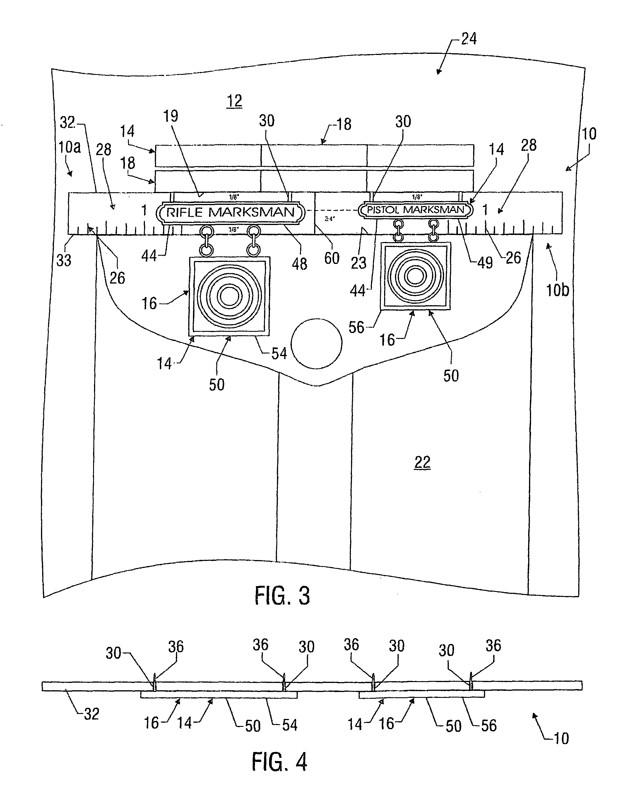
[0016]In some embodiments, the present disclosure involves an apparatus useful for properly positioning at least one badge on the front of a garment at least partially over a pocket of the garment. The badge includes at least first and second engagers extending therefrom for engagement with the garment. The apparatus includes a template removably positionable on the front of the garment at least partially above the pocket. The template includes at least one horizontal alignment indicator useful for centering the template relative to the pocket, a front face, at least one top edge and at least one bottom edge. A bottom edge of the template is alignable along a top edge of the pocket so that when the bottom edge of the template is aligned along the top edge of the pocket, the badge is properly positionable on the garment. At least one raised portion protrudes from the front face of the template, and is capable of seating at least a part of a first badge. When the corresponding first badge portion is seated by the raised portion(s), the first badge is properly positionable relative to the garment. At least one cut-out extends from at least one top edge of the template and terminates between the top edge and at least one bottom edge. First and second engagers of a first badge are moveable and positionable within the at least one cut-out and may be engaged with the garment therethrough. After the badge is properly positioned on the garment, the template is moveable away from the badge without disturbing the position of the at least one badge on the garment.
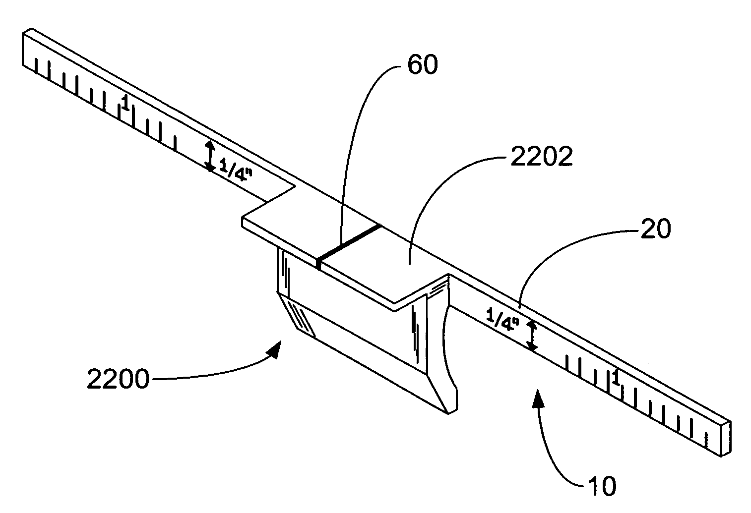
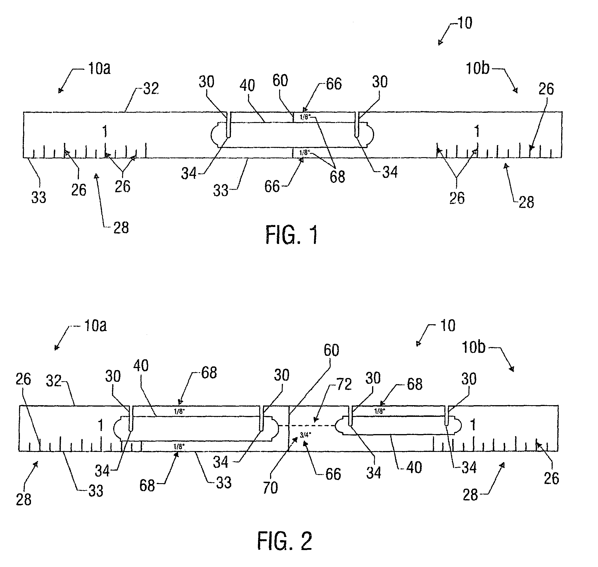
[0017]In various embodiments, the present invention involves a removable template useful for determining correct placement of at least one item at a desired location on the front of a carrier. The template is elongated and includes a single member without moving parts and a front face, top and bottom edges and left and right sides. First and second pairs of opposing measurement reference points are located proximate to the left and right sides of the template, respectively, and are useful for assisting in horizontally positioning the template on the front of the carrier. A first outline on the front face of the template is formed in the shape of at least part of a first item so that the first item may be positioned relative to the first outline for proper alignment of the first item over the template. At least one protruding portion extends from the front face and is associated with the first outline. The at least one protruding portion is capable of seating at least a part of the first item so that when the corresponding part of the first item is seated by at least one the protruding portion, the first item is properly positionable relative to the garment. First and second cut-outs each extend from the top edge of the template and provide large areas wherein first and second rear-facing pins of the first item are concurrently moveable, respectively, regardless of the distance between the pins and positions thereof on the first item. After the item is properly positioned upon and engaged with the carrier, the template may be moved downwardly and away from the tem and removed without disturbing the position thereof.
[0018]In many embodiments, the present invention involves a method for properly positioning at least a first item having at least first and second rear-facing engagers on the front of a garment at least partially over a pocket of the garment. This method utilizes an elongated template that includes at least one raised portion protruding from the front face thereof and which is capable of seating at least part of the first item on the template. A bottom edge of the template is aligned along a top edge of the pocket. The first item is placed at least partially onto the template so that a designated part of the first item is seated on the template by the raised portion(s). The first and second rear-facing engagers of the first item are placed through first and second cut-outs formed in the template and engaged with the garment. The template may be slid down and away from the at least first item without disturbing the position thereof.

Problems solved by technology

In positioning and locating one or more items on a carrier, difficulties may be encountered.
For example, the item(s) may be difficult or cumbersome to handle and / or precisely position because of the shape, configuration or small size of the item.
Precise positioning may also be difficult due to the small or awkward area or nature of the item where the item is to be placed.
When more than one item is required to be positioned, the small or differing sizes, shapes and or configurations of the items may be a hindrance to precisely locating and affixing the items.
Likewise, if the items are to be positioned proximate to one another, the close desired positioning of the items may make handling and precise positioning difficult.
If the precise positioning requires measuring distances or dimensions, making the correct measurements and / or effectively using such measurements may be difficult.
For another example, it may be unduly time-consuming to properly precisely position the item(s) on the carrier.
Thus, any of the above or other problems associated with precise positioning may be recurring frequently.

Method used


Image

  • Apparatus and methods for the placement of badges, ribbons and/or other items
  • Apparatus and methods for the placement of badges, ribbons and/or other items
  • Apparatus and methods for the placement of badges, ribbons and/or other items

Examples


Embodiment Construction

[0045]Characteristics and advantages of the present disclosure and additional features and benefits will be readily apparent to those skilled in the art upon consideration of the following detailed description and referring to the accompanying figures. It should be understood that the description herein and appended drawings are of various exemplary embodiments and are not intended to limit the appended claims or the claims of any patent or patent application claiming priority to this application. On the contrary, the intention is to cover all modifications, equivalents and alternatives falling within the spirit and scope of the claims. Many changes may be made to the particular embodiments and details disclosed herein without departing from such spirit and scope.

[0046]In the description below and appended figures, common or similar features are indicated by like or identical reference numerals or, in the absence of a reference numeral, are evident based upon the appended figures an...


PUM


Abstract

A template is provided for positioning at least one ribbon assembly on a garment at a predetermined position relative to the pocket. The template has a template body having a generally two-dimensional profile that is removably positionable on the front of the garment at least partially above the pocket. The template also has ribbon assembly positioning guides positioned on the template body to locate a predetermined position of a ribbon assembly on the garment in spaced relation with the pocket and with the template body. The ribbon assembly positioning guide includes a protrusion extending outwardly from the template and configured to support the ribbon assembly at a position at least partly coincidental with the predetermined position of the ribbon assembly. In other words, when the ribbon assembly is supported on the protrusion, the ribbon assembly is at least partly in the predetermined position.

Description

[0001]The present application claims the benefit of the filing date of, and is a continuation-in-part of, U.S. patent application Ser. No. 12 / 454,110, filed May 11, 2009, now issued as U.S. Pat. No. 8,112,898 B2 on Feb. 14, 2012; which claims priority to U.S. Provisional Application No. 61 / 051,710, filed May 9, 2008, and is a continuation-in-part of U.S. patent application Ser. No. 12 / 128,179, filed May 28, 2008, now issued as U.S. Pat. No. 7,637,028 on Dec. 29, 2009; which claims priority to U.S. Provisional Application No. 61 / 051,710, filed May 9, 2008, and is a continuation-in-part of U.S. patent application Ser. No. 11 / 726,583, filed on Mar. 22, 2007, now issued as U.S. Pat. No. 7,559,153 on Jul. 14, 2009; which claims priority to U.S. Provisional Patent Application No. 60 / 786,420, filed Mar. 27, 2006, the disclosures of all of which are hereby incorporated by reference herein in their entireties and for all purposes.FIELD OF THE DISCLOSURE[0002]The present disclosure relates ge...

Claims


Application Information

Patent Timeline
Patent Type & Authority Patents(United States)
IPC IPC(8): G01D21/00A44C3/00
CPCA44C3/002B25H7/02
Inventor ALLEN, MATTHEW BRIDGER
Owner VANGUARD IND EAST INC
Why Eureka
Try Eureka