

Electronic device
a technology of electronic devices and components, applied in the direction of printed circuits, sustainable manufacturing/processing, final product manufacturing, etc., can solve the problems of difficult relative positioning of boards with accuracy, affecting the outside dimension of electronic devices, and labor and adjustment costs
- Summary
- Abstract
- Description
- Claims
- Application Information
AI Technical Summary
Benefits of technology
Problems solved by technology
Method used
Image

Examples
first embodiment
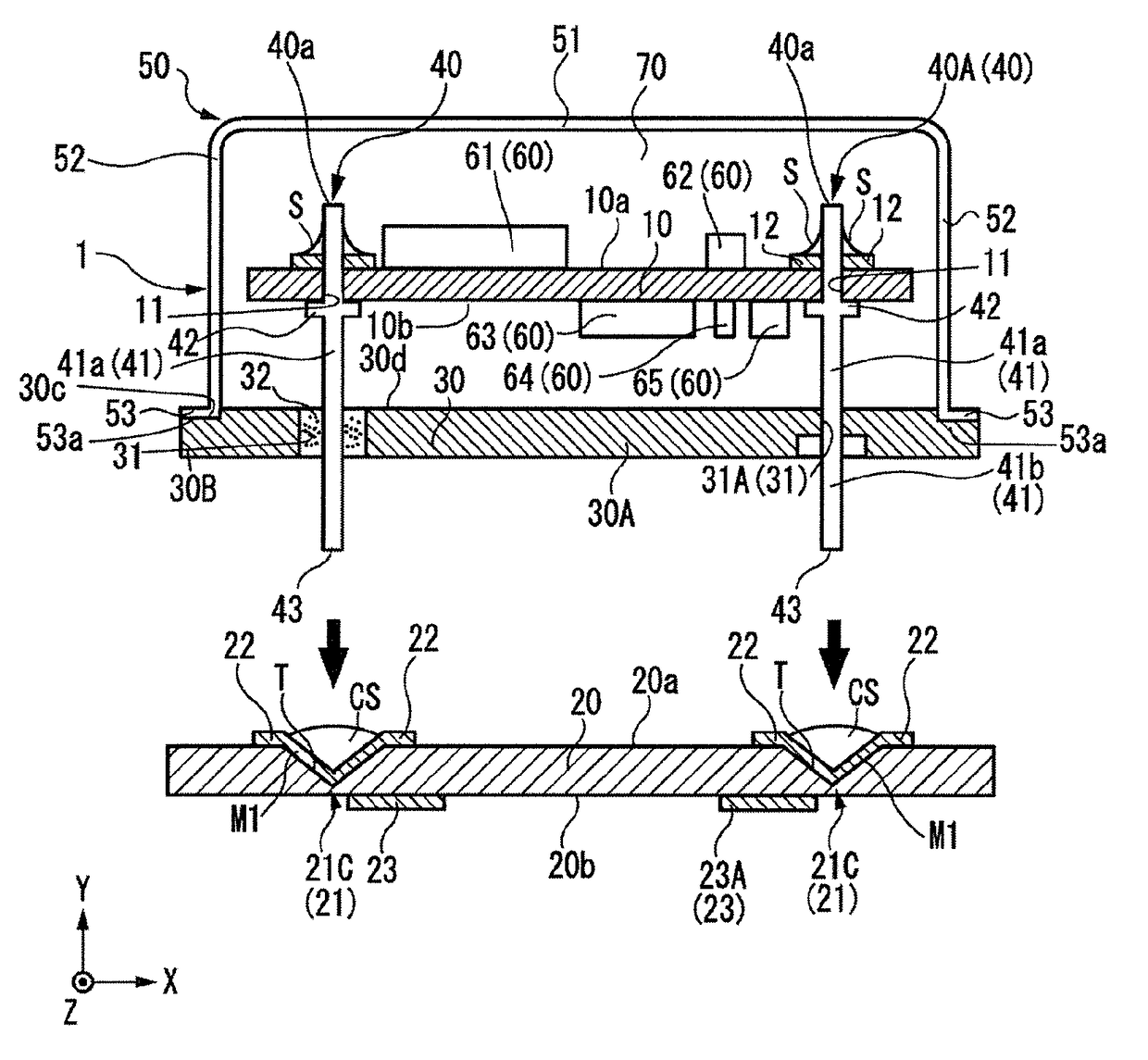
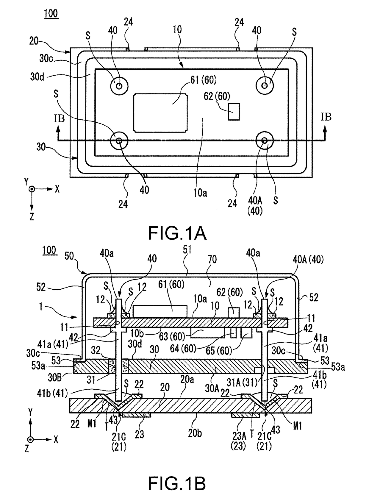
[0018]An example of an electronic device 100 according to an embodiment will be described using FIG. 1A and FIG. 1B. FIG. 1A is a plan view of the electronic device 100. FIG. 1B is a cross-sectional view taken along a line IB-IB in FIG. 1A. In FIG. 1A, a cover 50, which will be described later, is transparently illustrated. The electronic device 100 has a configuration of so-called surface mount type (Surface Mount Device: SMD) and is an oven controlled crystal oscillator (OCXO) that keeps an ambient temperature of a crystal resonator at constant. The same applies to other embodiments described later. The electronic device 100 includes an electronic device main body 1 and a second board (base plate) 20 as illustrated in FIG. 1A and FIG. 1B. The electronic device main body 1 includes a first board (base plate) 10.
[0019]The electronic device main body 1 is disposed on a +Y-side of the second board 20 and bonded to the second board 20. The electronic device main body 1 has a configurat...
first and second modification
[0046]The following describes configurations of the modifications according to the hole portion 21 of the second board 20 in the electronic device 100 of the first embodiment described above. In the following description, a component that is identical or equal to that of the above-described embodiment is indicated by the identical reference numeral, and the description thereof is omitted or simplified. FIG. 4A and FIG. 4B illustrate modifications of the configuration of the hole portion 21. FIG. 4A illustrates a hole portion 21A according to a first modification, and FIG. 4B illustrates a hole portion 21B according to a second modification.
[0047]As illustrated in FIG. 4A, the hole portion 21A according to the first modification includes the tapered surface T and a closed-bottom cylinder shaped surface T1 that further extends in the −Y-side from the end portion of the tapered surface T on the −Y-side. The closed-bottom cylinder shaped surface T1 is formed such that the distal end 43 ...
second embodiment
[0050]Subsequently, a second embodiment will be described with reference to FIG. 5. FIG. 5 is a cross-sectional view illustrating an example of an electronic device 200 according to the second embodiment. In the following description, a component that is identical or equal to that of the first embodiment is indicated by the identical reference numeral, and the description thereof is omitted or simplified. As illustrated in FIG. 5, the electronic device 200 includes the first board10, the second board 20, the support pillars 40, and the cover 50.
[0051]The electronic device 200 according to this embodiment has a configuration different from the above-described electronic device 100 in the point that the electronic device 200 does not include the third board 30. In the electronic device 200, the first board 10 is held separated from the second board 20 with the support pillars 40 raised from the front surface 20a of the second board 20. The bonding surface 53a of the cover 50 is bonded...
PUM
 Abstract
Description
Claims
Application Information