Robot arm

a robot arm and flexible technology, applied in the field of robot arms, can solve the problems of high force to be applied to the person being treated, high cost of hydraulic systems, and risk of contamination

Active Publication Date: 2013-01-29
FERROBOTICS COMPLIANT ROBOT TECH
View PDF33 Cites 10 Cited by
  • Summary
  • Abstract
  • Description
  • Claims
  • Application Information

AI Technical Summary

Benefits of technology

[0013]According to the system described herein, a robot arm may include the following features. The robot arm may include at least one pivotable lever. In an embodiment, the robot arm may be made up of at least two interlinked pivoted levers. Each pivoted lever has a constant length and is made up of a support, to one end of which a base is rigidly connected, and a pivotable piece is situated at its other end. The base of the second pivoted lever is rigidly connected to the pivotable piece of the first pivoted lever. The base of the next pivoted lever is rigidly connected to the pivotable piece of the previous pivoted lever. Pneumatic muscles are positioned between the base and the pivotable piece of one pivoted lever which may be used to actively set the particular pivot position. The force which the robot arm exerts externally is detected and limited by the controller of the robot arm. This detection and limitation is performed not only for the end of the robot arm, where a tool may be positioned,...

Problems solved by technology

Hydraulic systems are costly, heavy, often disseminate an odor of hydraulic oil, and entail the risk of contamination by escaping hydraulic fluid.
They are also dangerous as massage robots because an error in the hydraulic system can very rapidly cause dangerously high forces to be applied to the person being treated.
However, all of them have a very high purchase price, require a large amount of space, and have a menacing appearance.
In addition, they are very prone to damage with regard to a number of forces which can occur when moved by persons in connection with the massage due to linear guides arranged in a cascade-like manner.
It is disadvantageous that these drive elements are relatively heavy, space-consuming, and costly.
Despite the simple and robust structure, this design has so far not gained acceptance, pre...

Method used


Image

  • Robot arm
  • Robot arm
  • Robot arm

Examples


Embodiment Construction

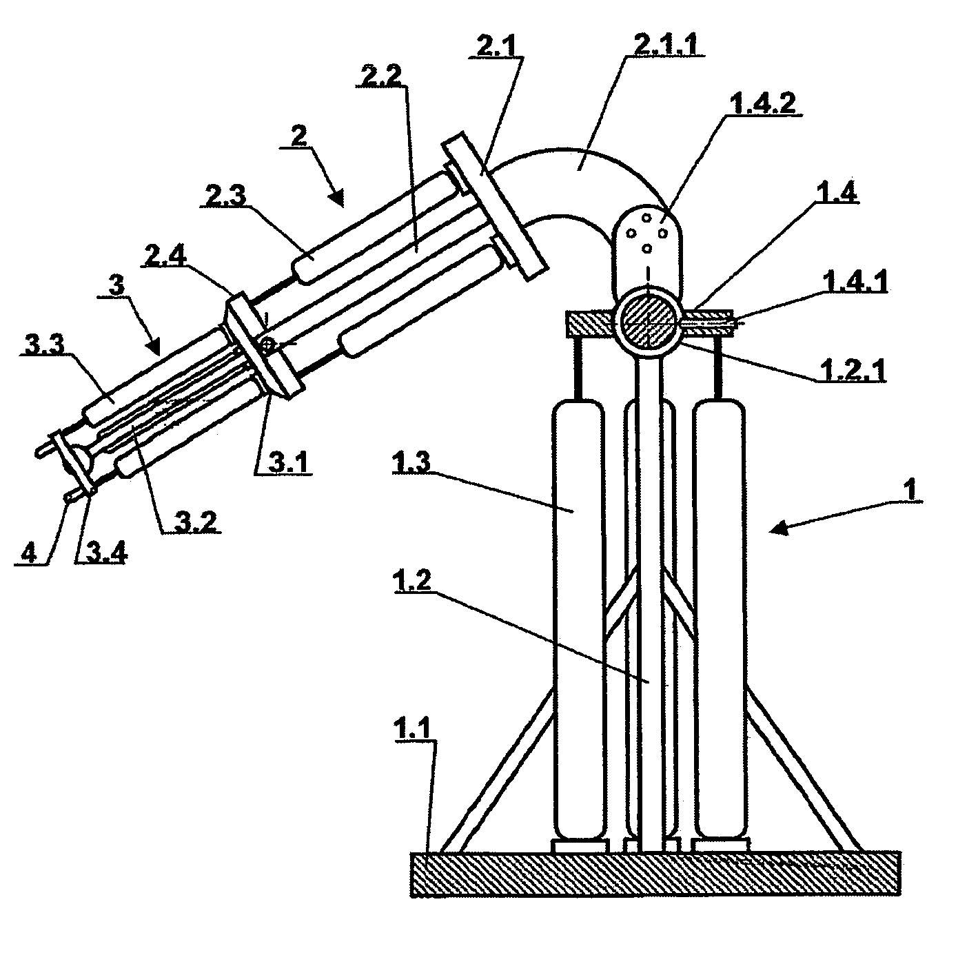
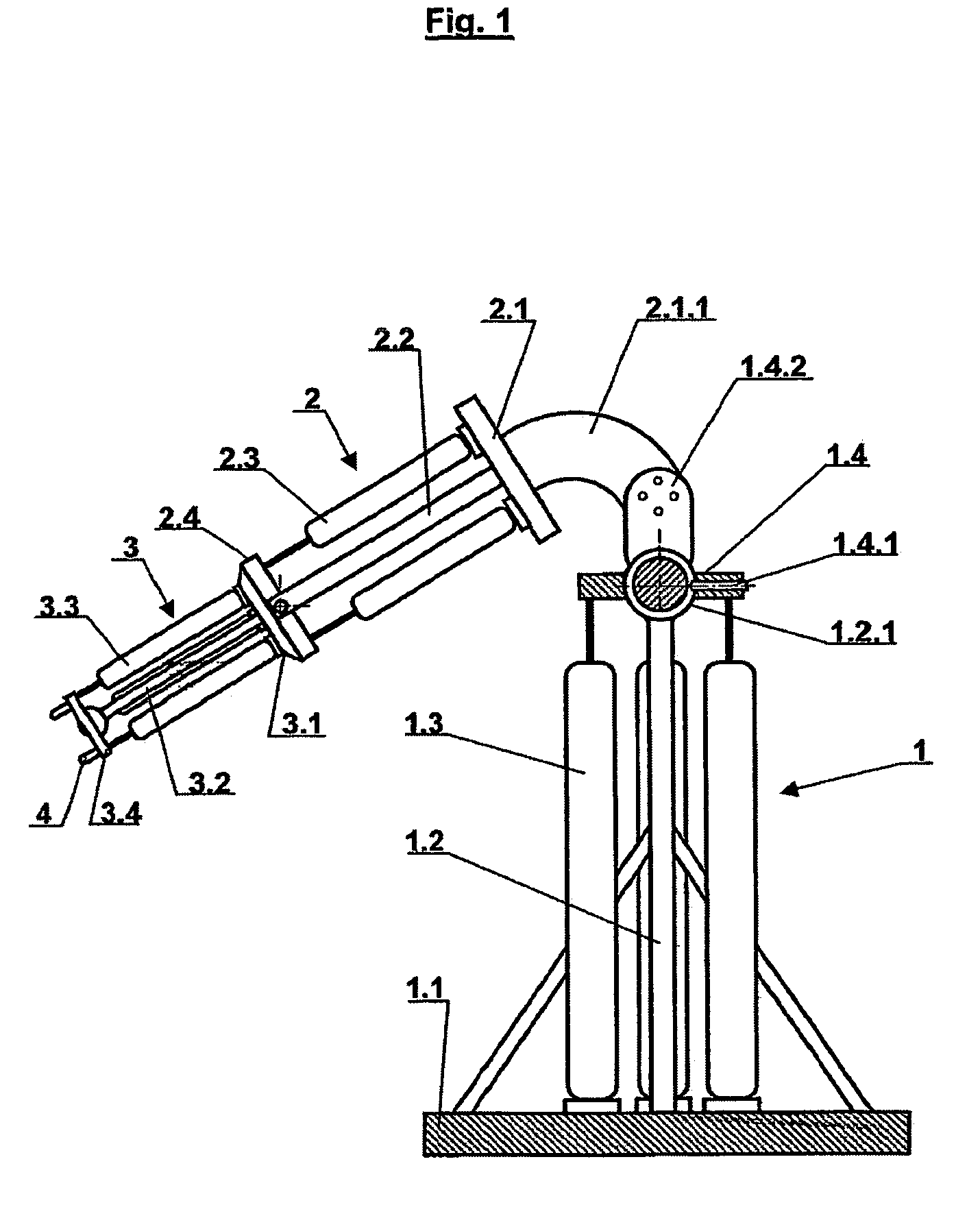
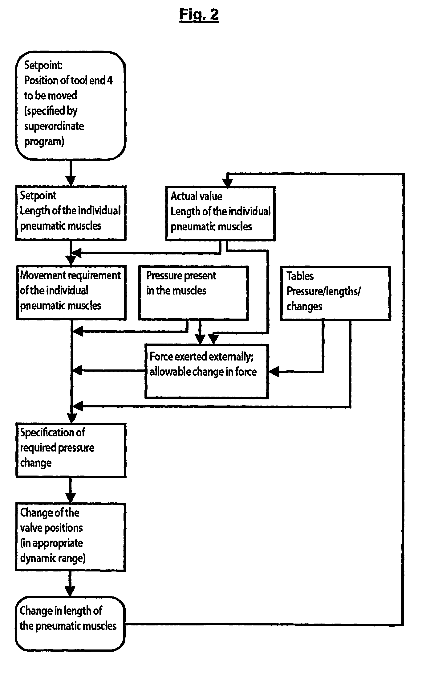
[0019]An embodiment of a robot arm according to the system described herein for the movement of a tool—as sketched in FIG. 1 and FIG. 2—will first be described in greater detail below. The embodiment of a robot arm according to the system described herein as a therapy device for passive and active mobilization of limbs will be described in greater detail further below.

[0020]Base 1.1 of first pivoted lever 1 supports the entire robot arm. It may stand on the floor of a room directly or on locking castors. However, it may also be attached to a bracket on a wall, to a machine, or to a fixture. It may also be situated on a platform which is moved controllably in the room or is mechanically pivotable about a vertical axis in relation to another base standing fixedly in the room. From base 1.1, support 1.2 rigidly joined to it projects upward and ends in ball 1.2.1 of a ball-and-socket joint. The socket of this ball-and-socket joint forms pivotable piece 1.4 of first pivoted lever 1. Thre...


PUM


Abstract

A robot arm formed from one or more optionally interlinked active pivoted levers, wherein a base is fixed to the one end of a support and a pivoting piece is pivotably mounted on the second end of the support with pneumatic muscles running form the base to the pivoting piece. Individual pneumatic muscles engage on opposing sides of the pivot axis of the pivoting piece and the base of a pivoting lever is fixed to the pivoting piece of the adjacent pivoting lever interconnected thereto. The controller measures the position of the individual pivoting levers and the pressure in the individual pneumatic muscles, calculates the externally acting forces from the pressure-distance diagrams for the individual pneumatic muscles and the geometric lever mechanical ratios for all pivoting levers and limits said forces.

Description

TECHNICAL FIELD[0001]This application relates to a flexible robot arm driven by pneumatic muscles.BACKGROUND OF THE INVENTION[0002]DE 3630822 C2 (Bridgestone) describes an arm pivotable about precisely one axis for an industrial robot. The arm is attached to a rotatably mounted belt pulley which is encompassed by a cable, a so-called pneumatic muscle being situated at both ends leading away from the belt pulley. A pneumatic muscle is made up of a tube-like center portion and two plate-like end pieces, at least one of which is provided with an air passage. When the tube-like center portion is inflated, its circumference is expanded and its length is reduced. This reduction in length can result from overcoming an external tensile force. When in the use case corresponding to DE 3630822 a pneumatic muscle is tightened, the arm is pivoted in a rotational direction; when this pneumatic muscle is released and the second pneumatic muscle is tightened, the arm is pivoted in the opposite dire...

Claims


Application Information

Patent Timeline
IPC IPC(8): A61H1/00A61H1/02A61H5/00
CPCA61H1/02A61H37/00A63B21/00178A63B23/12B25J9/1075B25J9/142A63B21/00069A63B21/0085A61H2001/0207A61H2201/018Y10T74/20305A63B23/1209A63B23/03508A63B21/4033
Inventor FERRARA, PAOLO
Owner FERROBOTICS COMPLIANT ROBOT TECH
Why Eureka
Try Eureka