Hinged fitting

a technology of hinges and fittings, applied in the direction of movable seats, manufacturing tools, gearing, etc., to achieve the effect of simple design and little construction spa

Inactive Publication Date: 2013-02-05
VOSS HANS WERNER
View PDF9 Cites 1 Cited by
  • Summary
  • Abstract
  • Description
  • Claims
  • Application Information

AI Technical Summary

Benefits of technology

[0012]It is therefore the object of the invention to provide a hinged fitting of the type mentioned at the beginning which retains its infinitely variably adjusted position even under high loading while having a simple design which requires little construction space.

Problems solved by technology

However, in the event of very high forces acting on the pivotable fitting part, as may occur during sharp decelerations of the vehicle, the frictional connection between the external taper and internal taper is overcome and therefore the pivotable component is inadvertently adjusted.

Method used


Image

  • Hinged fitting
  • Hinged fitting
  • Hinged fitting

Examples


Embodiment Construction

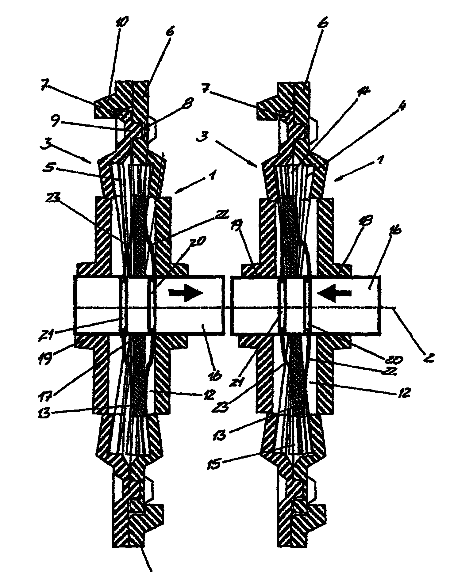
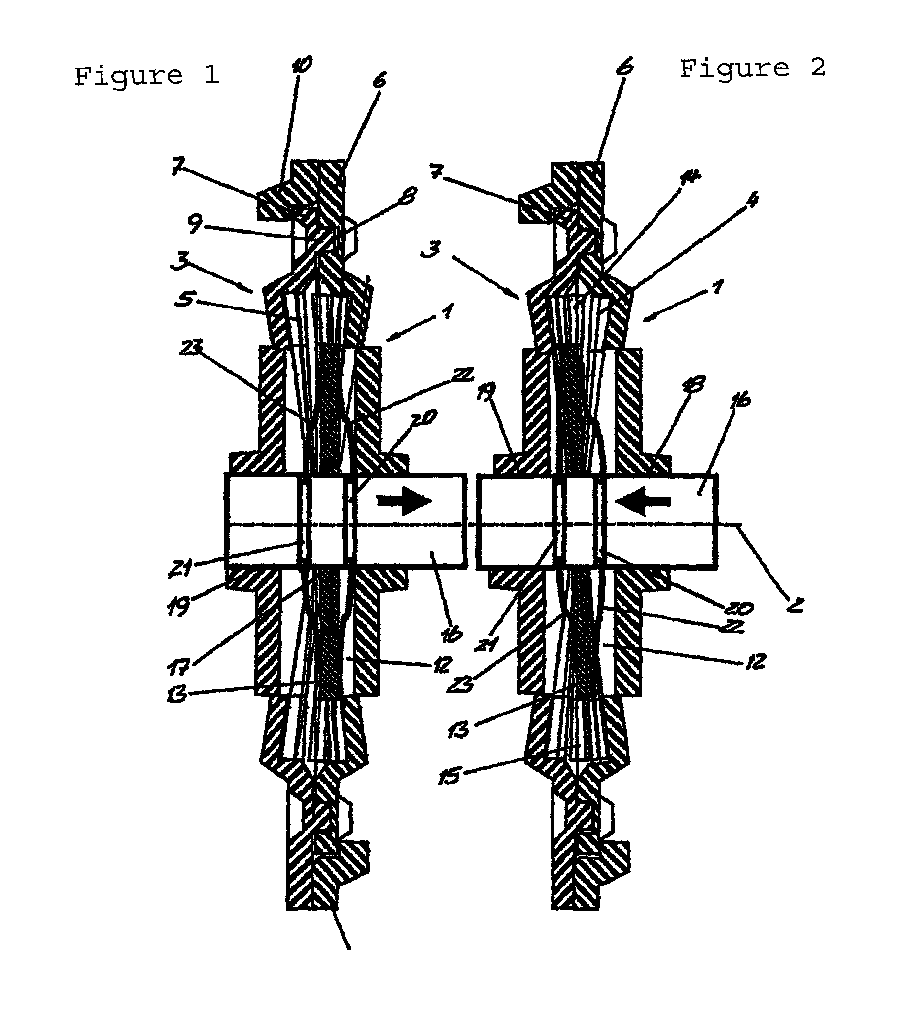
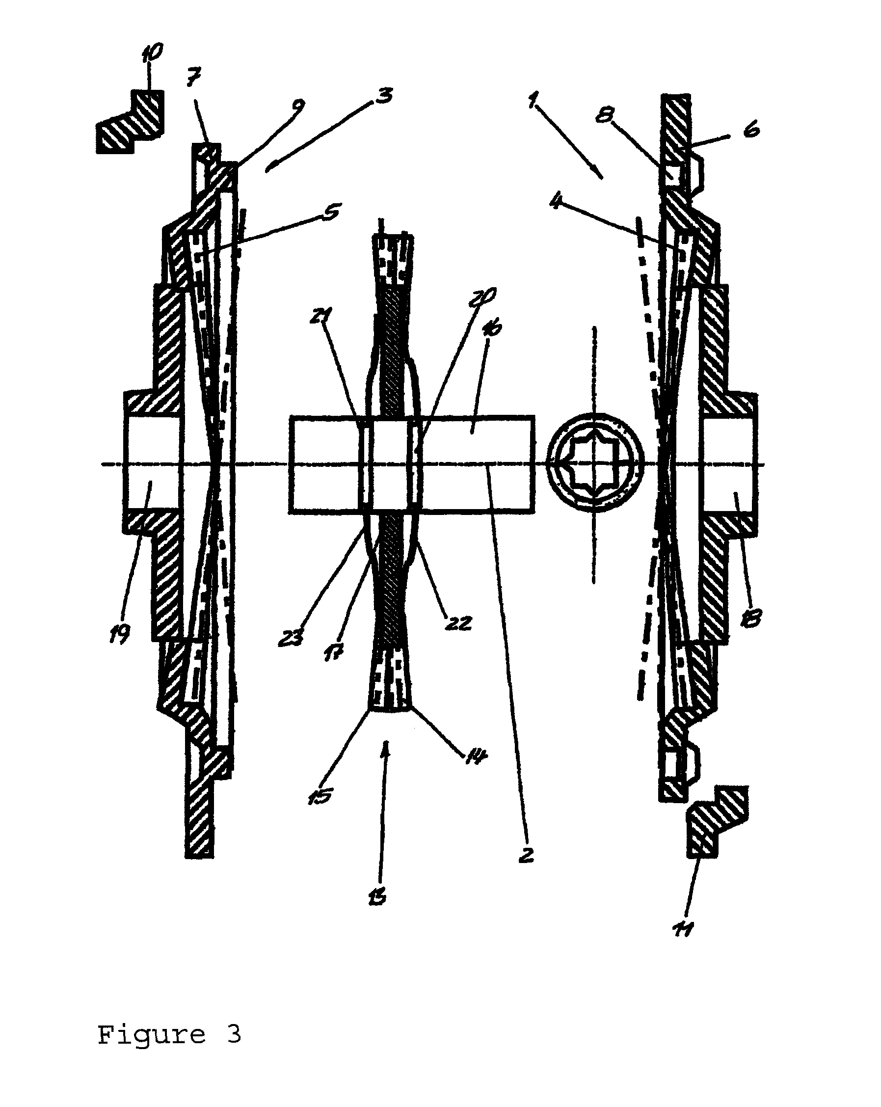
[0034]The hinged fitting illustrated in the figures has a first gear wheel 1, which is formed integrally with a fixed fitting part, and a pivotable fitting part which can be pivoted about a pivot axis 2 relative to the fixed fitting part and is formed integrally with a second gear wheel 3.

[0035]The first gear wheel 1 has an axially oriented toothing 4 and the second gear wheel 3 has a likewise axially oriented toothing 5, the two toothings 4 and 5 lying axially opposite each other and facing each other and preferably being designed as a bevel gear toothing.

[0036]The gear wheels 1 and 3 bear against each other by means of their annular regions 6 and 7 which are located radially outside the toothings 4 and 5 and face each other. In this case, an annular groove 8 is formed in the annular region 6 of the first gear wheel 1, which annular groove is open toward the annular region 7 of the second gear wheel 3, is concentric with respect to the pivot axis 2 and in which an axially protrudin...


PUM


Abstract

The invention relates to a hinged fitting for vehicle seats, having a fixed fitting part and a pivotable fitting part which are pivotably connected to each other about a swivel axis (2). The swivel movement of the pivotable component can be blocked in a stepless manner by a blocking device. A first blocking element (4) is connected in a nonrotatable manner to the fixed fitting part, and a second blocking element (5) is connected in a nonrotatable manner to the pivotable fitting part. Thereby the blocking elements which are positioned opposite each other coaxially to the swivel axis (2) can be coupled and decoupled to and from each other in a nonrotatable manner by means of an actuating unit.

Description

[0001]This nonprovisional application is a National Stage of International Application No. PCT / DE2007 / 000776, which was filed on May 2, 2007.BACKGROUND OF THE INVENTION[0002]1. Field of the Invention.[0003]The invention relates to a hinged fitting for a vehicle seat, with a fixed fitting part and a pivotable fitting part which are connected to each other in a manner such that they can pivot about a pivot axis, wherein the pivoting movement of the pivotable fitting part can be infinitely variably blocked by a blocking device, with a first blocking element which is connected in a rotationally fixed manner to the fixed fitting part, and a second blocking element which is connected in a rotationally fixed manner to the pivotable fitting part, wherein the blocking elements which lie opposite each other coaxially with respect to the pivot axis can be coupled to each other in a rotationally fixed manner and can be decoupled from each other by means of an actuating device.[0004]2. Descripti...

Claims


Application Information

Patent Timeline
Patent Type & Authority Patents(United States)
IPC IPC(8): B60N2/00B60N2/90
CPCB60N2/2252B60N2/2254F16H1/321B60N2/444Y10T16/5404B60N2/938
Inventor VOSS, HANS WERNER
Owner VOSS HANS WERNER
Why Eureka
Try Eureka