Aircraft dynamic pressure estimation system and method

a dynamic pressure estimation and aircraft technology, applied in the field of dynamic pressure measurement, can solve the problems of inaccurate aircraft airspeed being determined and displayed, blocked, and the flight control system not being able to receive inaccurate air data signals

Active Publication Date: 2013-02-12
HONEYWELL INT INC
View PDF12 Cites 6 Cited by
  • Summary
  • Abstract
  • Description
  • Claims
  • Application Information

AI Technical Summary

Problems solved by technology

It is thus undesirable for the flight control system to receive inaccurate air data signals.
Because the pitot tube opening faces forward, it can become blocked.
A blocked pitot tube can cause inaccurately sensed dynamic pressure and thus, for example, inaccurate aircraft airspeed being determined and displayed.
Presently, there are no back-up dynamic pressure sensors beyond the use of redundant pitot tubes, which are also susceptible to blockage.

Method used


Image

  • Aircraft dynamic pressure estimation system and method
  • Aircraft dynamic pressure estimation system and method
  • Aircraft dynamic pressure estimation system and method

Examples


Embodiment Construction

[0012]The following detailed description is merely exemplary in nature and is not intended to limit the invention or the application and uses of the invention. Furthermore, there is no intention to be bound by any theory presented in the preceding background or the following detailed description.

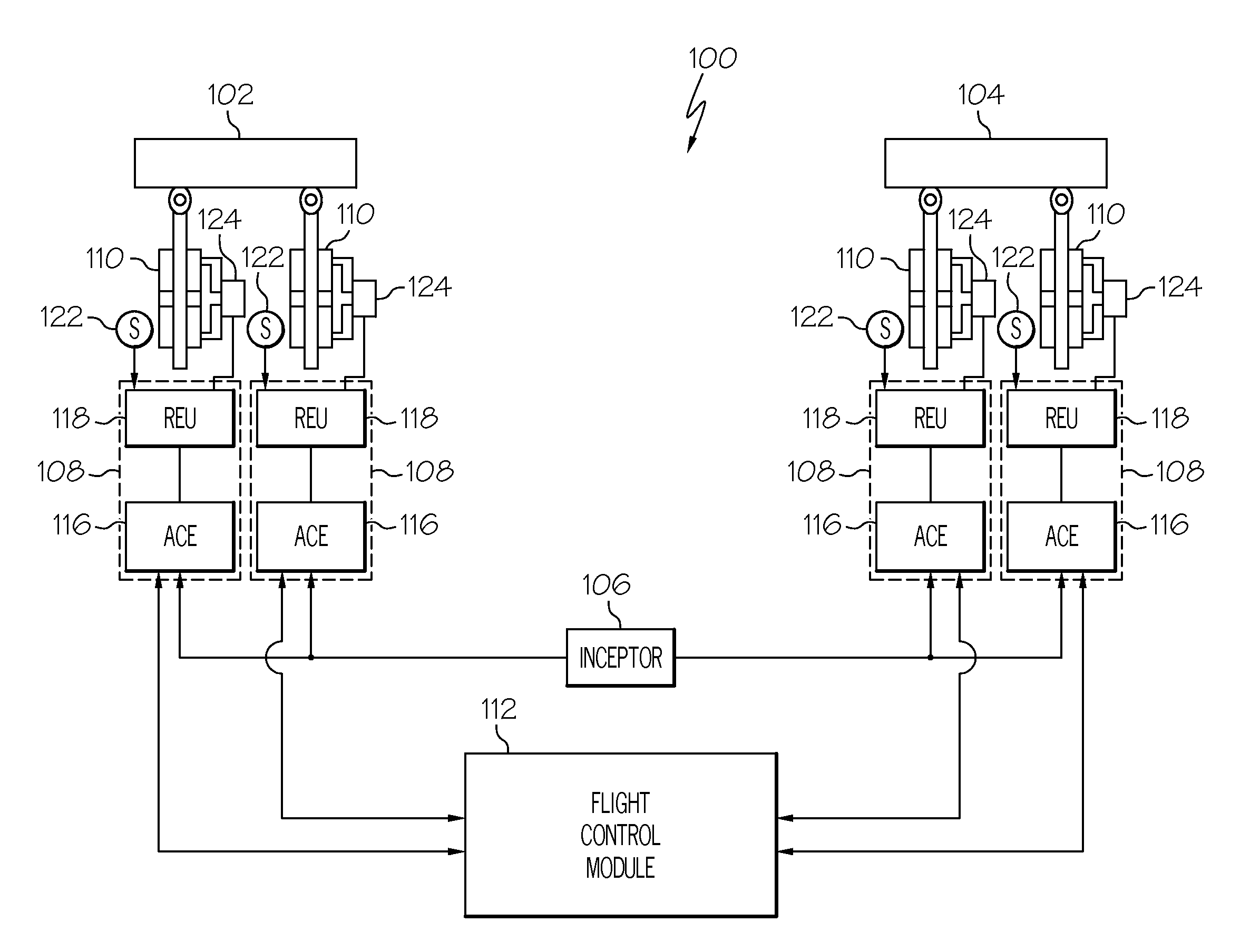
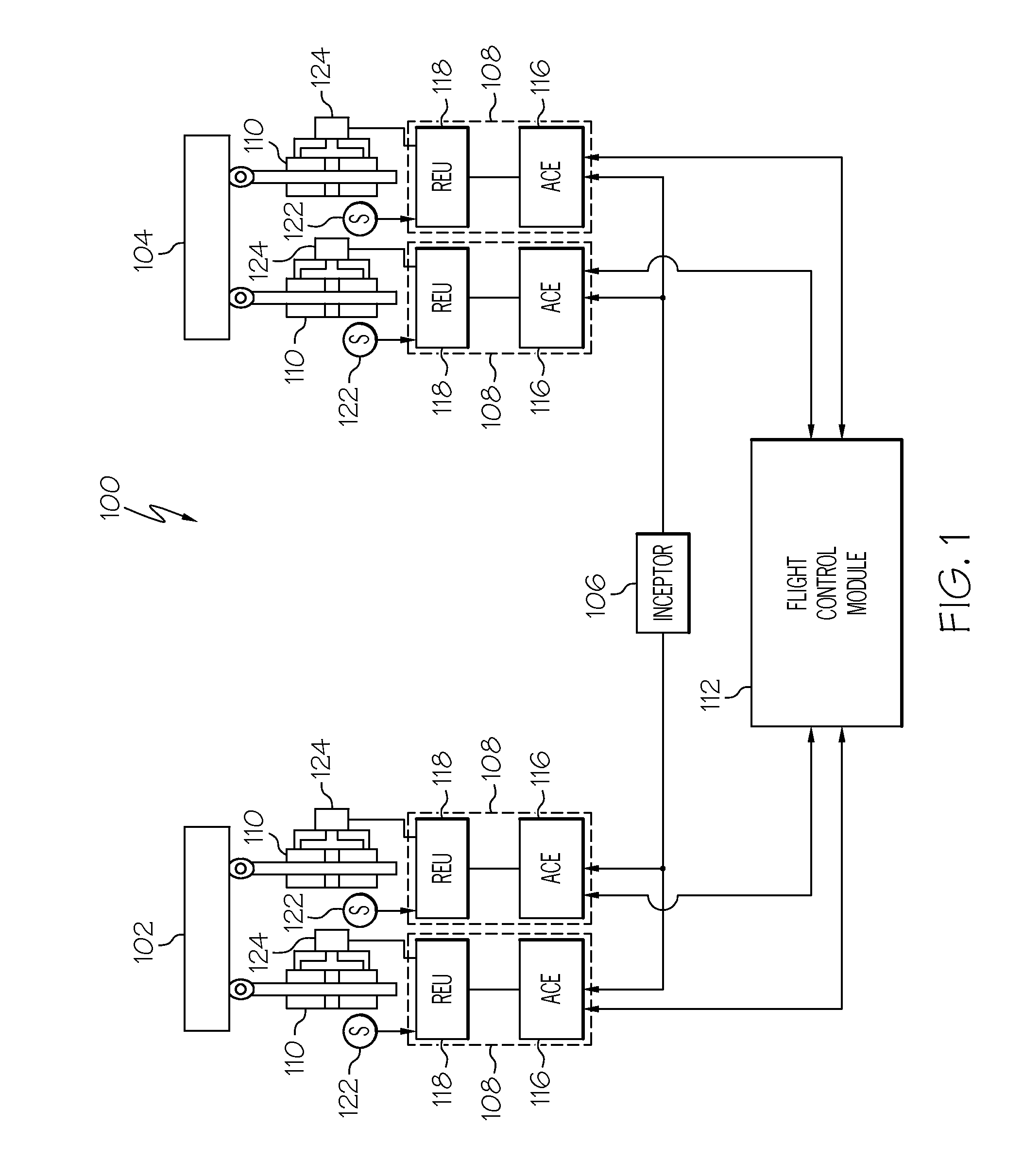
[0013]Referring first to FIG. 1, a functional block diagram of a portion of an aircraft flight control surface actuation system 100 is depicted. In particular, that portion of a flight control surface actuation system 100 that controls the position of two flight control surfaces—a left aileron 102 and a right aileron 104—is depicted. The depicted portion of the flight control surface actuation system 100 includes an inceptor 106, a plurality of actuator controls 108, a plurality of flight control surface actuators 110, and a flight control module 112.

[0014]The inceptor 106 is configured to move in response to an input force supplied from, for example, a pilot. One or more non-illustrated pos...


PUM

PropertyMeasurementUnit
dynamic pressureaaaaaaaaaa
pressureaaaaaaaaaa
hydraulic pressureaaaaaaaaaa

Abstract

Methods and apparatus are provided for estimating aircraft dynamic pressure. The load on the flight control surface actuator that is coupled to a flight control surface is measured. An estimate of the aircraft dynamic pressure is calculated from the measured load.

Description

TECHNICAL FIELD[0001]The present invention generally relates to dynamic pressure measurement and, more particularly, to a system and method for calculating an estimate of aircraft dynamic pressure from flight control surface actuator load sensors.BACKGROUND[0002]Many modern flight control systems rely on various air data parameters, such as dynamic pressure, to calculate aircraft control commands. It is thus undesirable for the flight control system to receive inaccurate air data signals. Typically, dynamic pressure is sensed using one or more pitot tubes. Most often, a pitot tube is located on the wing or front section of an aircraft, with its opening facing forward. As aircraft airspeed varies, ram air pressure at the pitot tube opening also varies. The pressure variations can thus be used to determine and indicate aircraft airspeed.[0003]Because the pitot tube opening faces forward, it can become blocked. The sources of potential blockage are numerous and varied, and include ice,...

Claims


Application Information

Patent Timeline
Patent Type & Authority Patents(United States)
IPC IPC(8): G06F19/00B64C13/00G01L15/00
CPCG01P5/14
Inventor HICKMAN, ALAN BRUCE
Owner HONEYWELL INT INC
Why Eureka
Try Eureka