Limited authority and full authority mode fly-by-wire flight control surface actuation control system

a control system and flight control technology, applied in process and machine control, instruments, navigation instruments, etc., can solve the problems of increasing the overall implementation cost of such systems, and the inability of presently known fly-by-wire system configurations to integrate with other functionalities

Inactive Publication Date: 2009-06-18
HONEYWELL INT INC
View PDF19 Cites 22 Cited by
  • Summary
  • Abstract
  • Description
  • Claims
  • Application Information

AI Technical Summary

Benefits of technology

[0007]In one embodiment, and by way of example only, an aircraft flight control surface actuation control system includes an actuator control unit and a flight control module. The actuator control unit includes at least two independent actuator control channels. Each independent actuator control channel is coupled to receive pilot inceptor position signals and flight control augmentation data. Each independent actuator control channel is operable to generate limited authority flight control surface actuator commands based on the pilot inceptor position signals and the flight control augmentation data. The flight control module is in operable communication with the actuator control unit. The flight control module is configured to supply the flight control augmentation data to each of the independent actuator control channels, determine operability of each of the actuator control channels, and, based on the determined operability of each independent actuator control channel, to selectively prevent one of the independent actuator control channels from supplying the limited authority flight control surface actuator commands.
[0008]In another exemplary embodiment, an airc

Problems solved by technology

These standards can also lead to increased overall implementation costs for such systems, including fly-by-wire systems.
However, presen

Method used


Image

  • Limited authority and full authority mode fly-by-wire flight control surface actuation control system
  • Limited authority and full authority mode fly-by-wire flight control surface actuation control system
  • Limited authority and full authority mode fly-by-wire flight control surface actuation control system

Examples


Embodiment Construction

[0014]The following detailed description is merely exemplary in nature and is not intended to limit the invention or the application and uses of the invention. Furthermore, there is no intention to be bound by any theory presented in the preceding background or the following detailed description. In this regard, although much of the invention is depicted and described as being implemented in fixed-wing aircraft, the invention may also be used in rotary-wing aircraft.

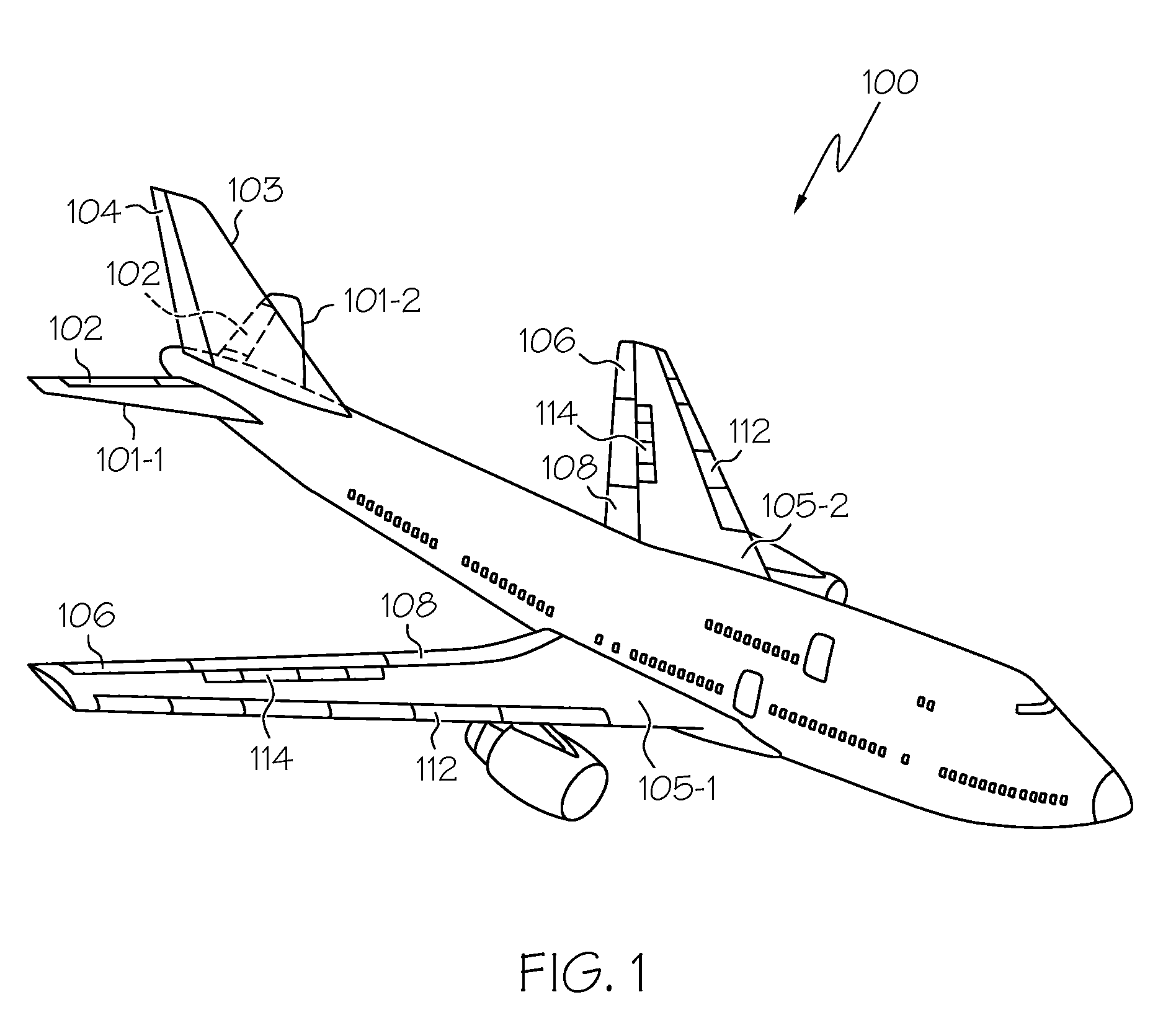
[0015]Turning now to FIG. 1, a perspective view of an exemplary aircraft is shown. In the illustrated embodiment, the aircraft 100 includes first and second horizontal stabilizers 101-1 and 101-2, respectively, a vertical stabilizer 103, and first and second wings 105-1 and 105-2, respectively. An elevator 102 is disposed on each horizontal stabilizer 101-1, 101-2, a rudder 104 is disposed on the vertical stabilizer 103, and an aileron 106 is disposed on each wing 105-1, 105-2. In addition, a plurality of flaps 108, slat...


PUM


Abstract

An aircraft flight control surface actuation control system includes an actuator control unit and a flight control module. The actuator control unit includes at least two independent actuator control channels to generate limited authority flight control surface actuator commands based on pilot inceptor position signals and flight control augmentation data. The flight control module supplies the flight control augmentation data to each of the independent actuator control channels, determines operability of each of the actuator control channels and, based on the determined operability of each independent actuator control channel, selectively prevents one of the independent actuator control channels from supplying the limited authority flight control surface actuator commands. The flight control module may also generate full authority flight control surface actuator commands for supply to flight control surface actuators.

Description

TECHNICAL FIELD[0001]The present invention generally relates to aircraft flight control and, more particularly, to a multi-authority mode fly-by-wire flight control surface actuation control system.BACKGROUND[0002]Aircraft typically include a plurality of flight control surfaces that, when controllably positioned, guide the movement of the aircraft from one destination to another. The number and type of flight control surfaces included in an aircraft may vary, but typically include both primary flight control surfaces and secondary flight control surfaces. The primary flight control surfaces are those that are used to control aircraft movement in the pitch, yaw, and roll axes, and the secondary flight control surfaces are those that are used to influence the lift or drag (or both) of the aircraft. Although some aircraft may include additional control surfaces, the primary flight control surfaces typically include a pair of elevators, a rudder, and a pair of ailerons, and the seconda...

Claims


Application Information

Patent Timeline
IPC IPC(8): G05D1/00
CPCG05D1/0061B64C13/503B64C13/505
Inventor YOUNT, LARRY J.KELLEY, GERALD B.STANGE, KENT A.POND, WELSH C.
Owner HONEYWELL INT INC
Why Eureka
Try Eureka