Personal electronic device holder

a technology for electronic devices and holders, applied in the direction of machine supports, transportation and packaging, other domestic objects, etc., can solve the problems of prior art mounting, difficult to find, and common for individuals to suffer anxiety

Inactive Publication Date: 2013-02-19
CICCO MIKE
View PDF9 Cites 12 Cited by
  • Summary
  • Abstract
  • Description
  • Claims
  • Application Information

AI Technical Summary

Problems solved by technology

The use of the personal electronic device has become such a part of personal daily use that it is common for an individual to suffer anxiety if he realizes too late that he has left home and forgotten his cell phone.
This, however, can also make them difficult to find if the user has set them down.
Much like forgetting where the car keys are, the remote control to the television or forgetting where the wallet and check book are, it can be a challenge to always remember the location of the hand held personal electronic device.
Unfortunately, however, there are problems with prior art mounts.
One problem is that prior art mounts are designed to function in a specific single location.
For example an indoor stand will not mount appropriately in an automobile and, likewise, a mount for placement in an automobile air vent cannot be used to mount a device on a user's desk.
Also, modern smart phones and mobile devices are constantly releasing new applications making it necessary for the user to have his mobile device ready and available at all times. There are currently no device mounts that allow for the user to have constant access to his mobile device to accommodate the ever increasing number of software applications.
Additionally, prior art mounts tend to clamp the cell phone in such a manner that buttons and controls on the sides of the cell phone are obscured.
Each of the mounting devices shown in these prior art patents include clamps that are large and unwieldy and are likely to obscure controls and buttons on the side of a user's cell phone, making it difficult to properly operate the mounted cell phone.

Method used


Image

  • Personal electronic device holder
  • Personal electronic device holder
  • Personal electronic device holder

Examples


Embodiment Construction

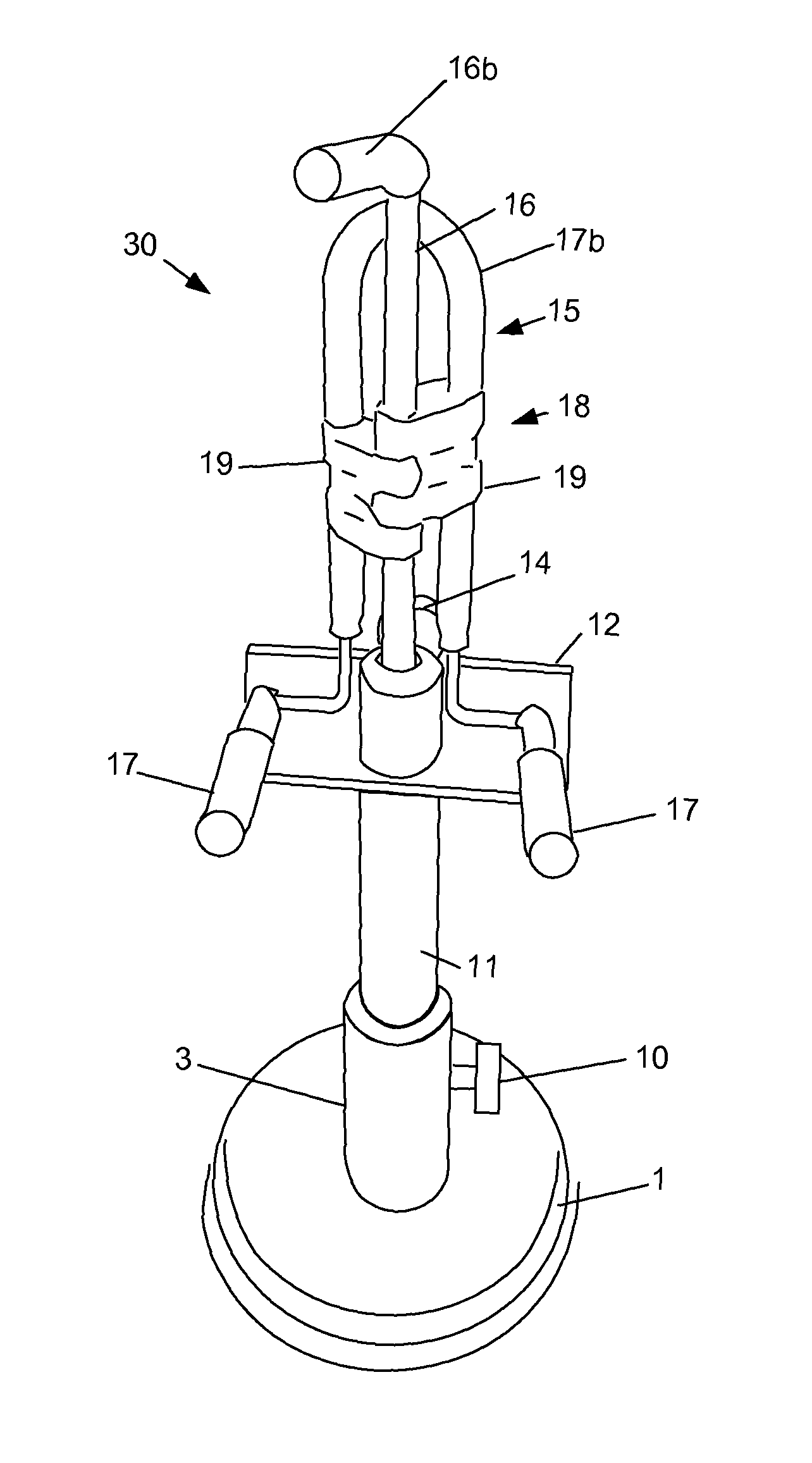
[0027]FIG. 1 shows a perspective view of a preferred embodiment of the present invention. In the preferred embodiments, a personal electronic device such as a cell phone is mounted between upper adapter arm 16b and lower adapter arms 17. Then, adapter 15 may be inserted into pedestal 11 (FIG. 1) or adapter 15 may be connected to a third party mounting device such as mount 60 (FIGS. 8 and 11).

Attachment of Adapter to the Pedestal and Weighted Base

Weighted Base

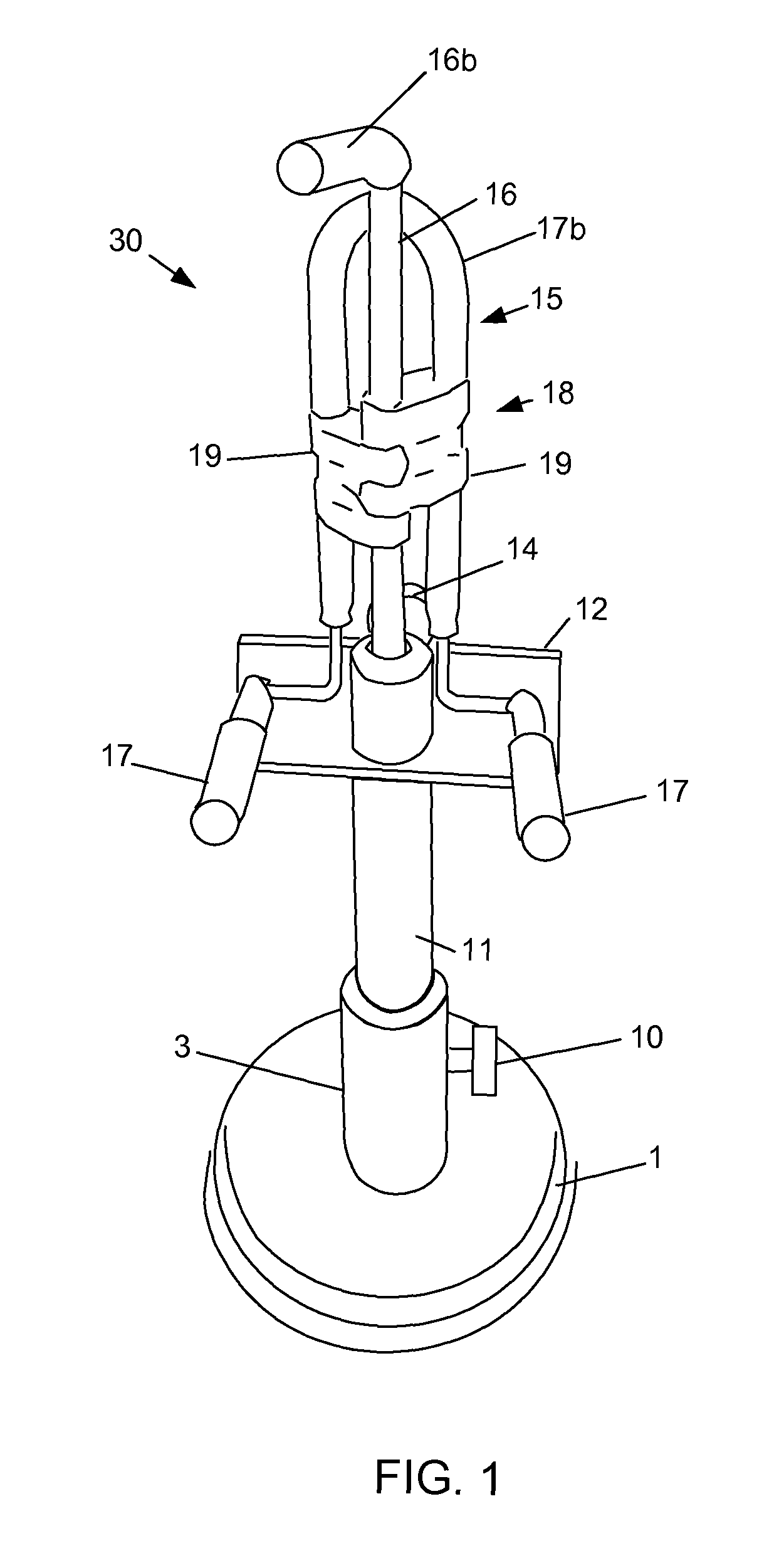
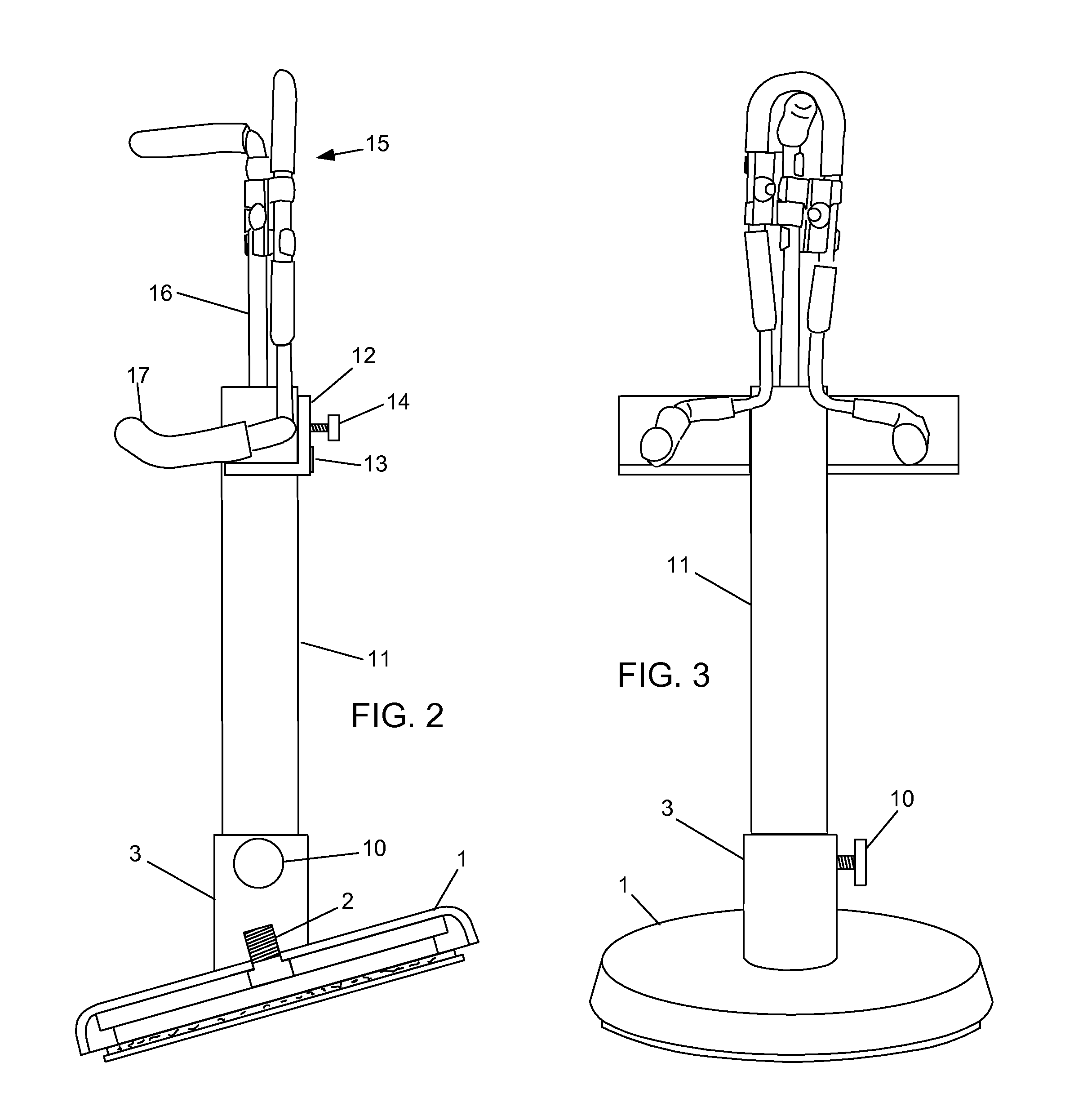
[0028]Base 1 is connected to base fitting 3 via base screw 2 (FIGS. 2, 4). Metal weight 4 is rigidly connected to base screw 2 as shown in FIG. 4. In a preferred embodiment, base screw 2 is press fit into metal weight 4 for the press fit. Base magnet 5 is connected to metal weight 4 via magnetic force. Rubbery padding 6 is adhesively attached to metal plate 7 (FIG. 4B). Adhesive layer 8 is connected to the bottom side of metal plate 7. Wax paper 8b covers adhesive layer 8 until adhesive layer 8 is needed.

Base Fitting

[0029]As sho...


PUM


Abstract

The present invention provides a portable electronic device holder. A lower adapter support piece supports two lower adapter arms. An upper adapter arm is supported by a adjustable rod. An adjustment fitting is connected to the lower adapter support piece and the adjustable rod is slidingly connected to the adjustment fitting and can be slid up and down by utilization of finger force. A portable electronic device is mounted and held secure as it is squeezed between the upper adapter arm and the two lower adapter arms. In a preferred embodiment the portable electronic device holder is mounted by either inserting the adjustable rod into a hollow pedestal attached to a base or by attaching the lower adapter arm support piece to a dual T mount of a separate mounting device.

Description

[0001]The present invention relates to personal electronic devices, and in particular, to personal electronic device holders.BACKGROUND OF THE INVENTION[0002]In recent years hand held portable electronic devices (i.e., cell phones, GPS units, portable game consoles, Personal Digital Assistants (PDA's)) have become increasingly popular. For example, fifteen years ago cell phones were used by CEO's and business executives to track meetings and stock market performance. Now it is common for every member of a family to have their own cell phone with children as young as 8 or 9 carrying them to school. Moreover, the technology of the portable electronic device has blended. No longer is a cell phone just a cell phone, a PDA just a PDA or a portable hand held game console just for playing personal video games. The technologies are intertwined and a user can now use his “cell phone” to make a phone call, upload pictures, play a video game, track his location using a built in Global Position...

Claims


Application Information

Patent Timeline
Patent Type & Authority Patents(United States)
IPC IPC(8): F16M11/00
CPCB60R11/02F16M13/00H04M1/04B60R2011/0005B60R2011/0028B60R2011/0056B60R2011/0071B60R2011/0078B60R2011/0082F16M11/041F16M11/08F16M11/126F16M13/022
Inventor CICCO, MIKE
Owner CICCO MIKE
Why Eureka
Try Eureka