
Mechanical jig

a mechanical and jig technology, applied in the field of mechanical jigs, can solve the problems of high preparation time, stress on the joint, and significant amount of skill and experience to create such a join

Inactive Publication Date: 2013-02-19
ZANDER PETER JACKSON
View PDF51 Cites 8 Cited by
  • Summary
  • Abstract
  • Description
  • Claims
  • Application Information

AI Technical Summary

Benefits of technology

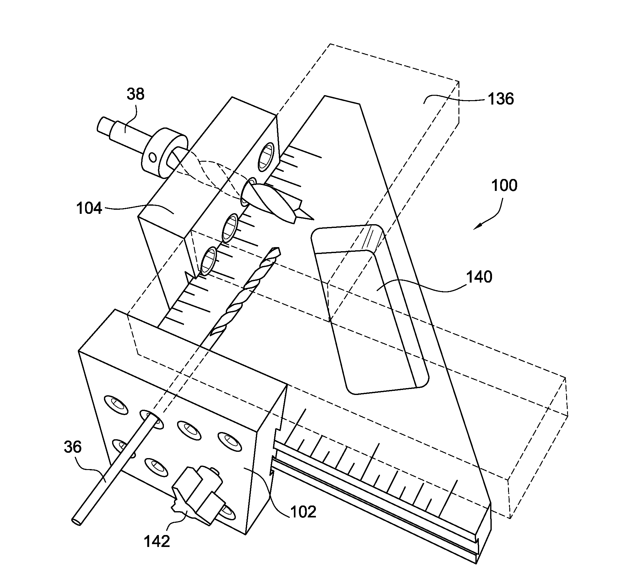
The present invention provides a jig for drilling intersecting holes in a work piece. The jig includes a body with at least one bolt-hole guide and at least one barrel-nut hole guide, which are perpendicular and intersecting with each other. The jig can be L-shaped and has edges that align with a portion of the work piece. The jig also includes templates that can be moved along two or three mutually orthogonal axes of a base and have upper and lower sets of bolt-hole guides and barrel-nut guides at different heights to accommodate different work piece thicknesses. The templates can include blocks with apertures to receive drill bits. The use of the jig simplifies the process of drilling intersecting holes in the work piece and reduces the time and effort required for the operator.

Problems solved by technology

A problem with the mortise and tenon joint is that the wood must be straight-grained stock to avoid breakage, resulting from stress on the joint.
Another problem with the mortise and tenon joint is that it requires a large amount of preparation time to produce the joint, including requiring several calculations and drawing layouts.
Further, a significant amount of skill and experience is required to create such a joint.
While specialty tools, such as chain mortisers and horizontal boring machines, can create these joints more quickly, they require a significant investment because the tools are expensive.

Method used


Image

  • Mechanical jig
  • Mechanical jig
  • Mechanical jig

Examples


Embodiment Construction

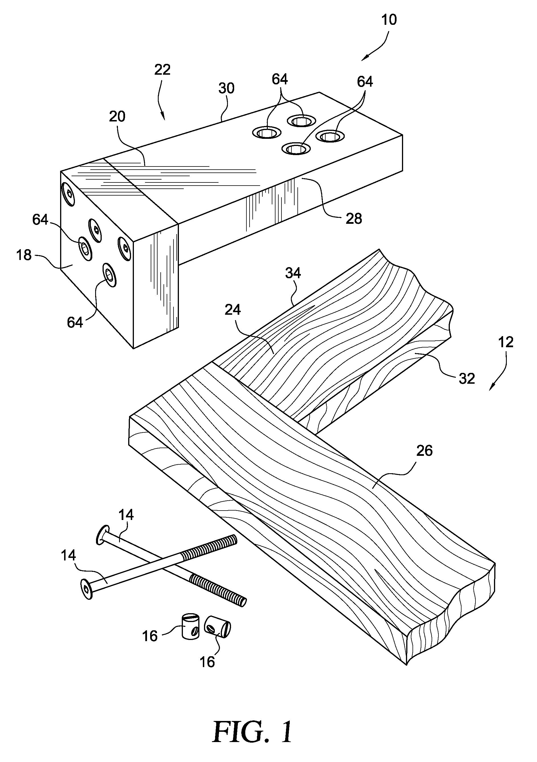
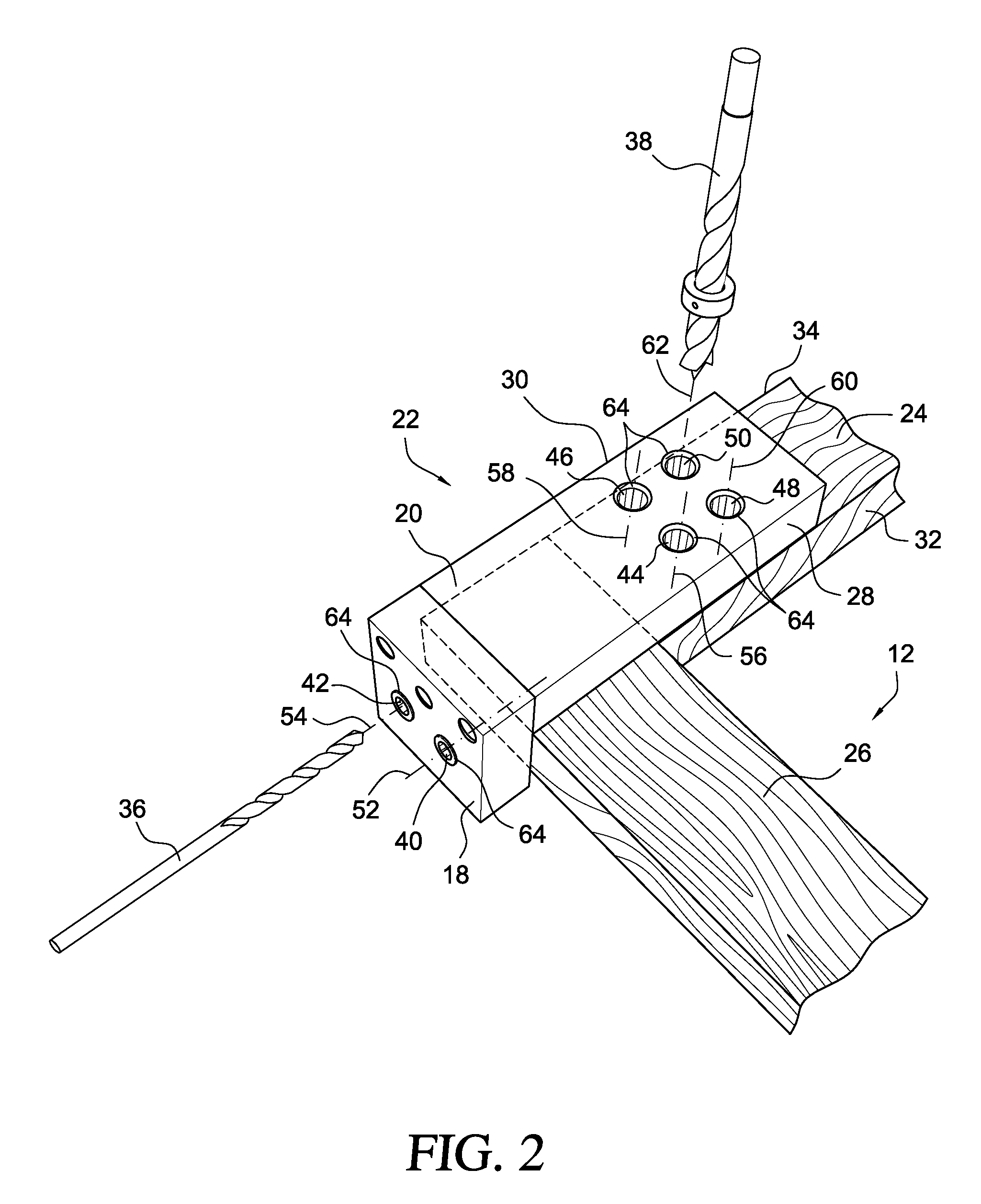
[0028]Referring to the Figures, FIGS. 1-4 show an embodiment of the present invention showing a jig 10 which provides a template for drilling intersecting holes in a work piece 12. A bolt 14 and a barrel-nut 16 are then inserted into each set of intersecting holes to fasten two portions 18, 20 of the work piece 12 together. The jig 10 includes a body 22 having two template portions 18, 20, wherein the two template portions 18, 20 are arranged in an L-shaped configuration. The body 22 is preferably constructed of hard plastic, aluminum or injection molded plastic. In an embodiment of the invention, the body 22 can include two separate, but contiguous template portions 18, 20. Alternatively, the template portions 18, 20 can be an integral part of the body 22.

[0029]In an embodiment of the invention, the jig 10 is sized to have a width corresponding to a typical width of a rail 24 and stile 26 in frame-and-panel construction cabinetry. That is, cabinetry stock is typically three-quarter...


PUM

PropertyMeasurementUnit
thickaaaaaaaaaa
thickaaaaaaaaaa
diameteraaaaaaaaaa

Abstract

A jig for drilling intersecting holes in a work piece. The jig comprises a base for supporting the work piece and a first template operatively coupled to the base and having a bolt-hole guide located along a first axis of the template, the bolt-hole guide having a diameter sized to receive a first drill bit. The jig also includes a second template operatively coupled to the base and having a barrel-nut hole guide located along a second axis of the template, perpendicular and intersecting the first axis. The barrel-nut hole guide has a diameter larger than the diameter of the bolt-hole guide and is sized to receive a second drill bit.

Description

CROSS-REFERENCE TO RELATED APPLICATIONS[0001]Not applicable.STATEMENT REGARDING FEDERALLY SPONSORED RESEARCH OR DEVELOPMENT[0002]Not applicable.REFERENCE TO A “SEQUENCE LISTING”[0003]Not applicable.BACKGROUND OF THE INVENTION[0004]1. Field of the Invention[0005]The present invention relates generally to a mechanical jig for drilling intersecting holes in a work piece, and more particularly for a jig having a bolt-hole guide aligned along a first axis and a barrel-nut guide having a diameter greater than the bolt-hole guide and aligned along a second axis, which is perpendicular and intersecting to the first axis.[0006]2. Description of Related Art[0007]A mortise and tenon joint is a traditional joint often used to join together two pieces of wood. This joint creates a strong connection between the two pieces that are frequently at right angles to one another. This joint is preferred for a broad range of applications from making fine furniture to assembling massive timber frames for ...

Claims


Application Information

Patent Timeline
Patent Type & Authority Patents(United States)
IPC IPC(8): B25B3/00B23B47/00B23B45/14B23B47/28B25B1/20B23B49/02B23G1/00B23G1/48B23B49/00
CPCB23B47/287B23B2247/12B23B2260/004Y10T408/567B23B2260/12Y10T408/56245B23B2260/0482
Inventor ZANDER, PETER JACKSON
Owner ZANDER PETER JACKSON
Learn More