
MEMS wavelength converting lighting device and associated methods

a technology of wavelength conversion and lighting device, applied in the field of lighting devices, can solve problems such as risk of visual flicker, and achieve the effect of reducing complexity, size and manufacturing expens

Active Publication Date: 2013-02-26
HEALTHE INC
View PDF105 Cites 36 Cited by
  • Summary
  • Abstract
  • Description
  • Claims
  • Application Information

AI Technical Summary

Benefits of technology

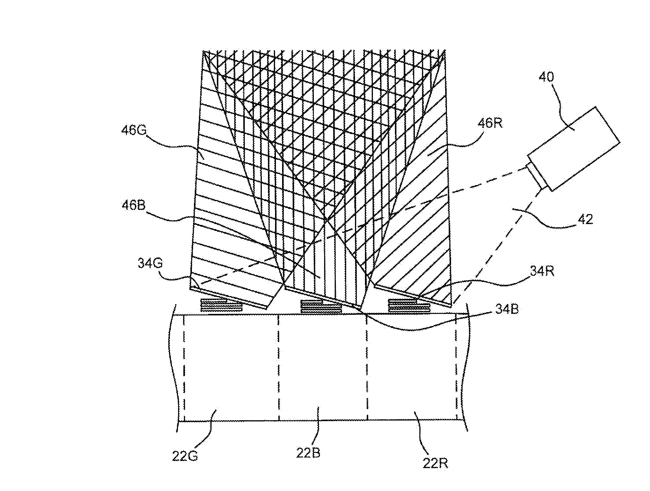
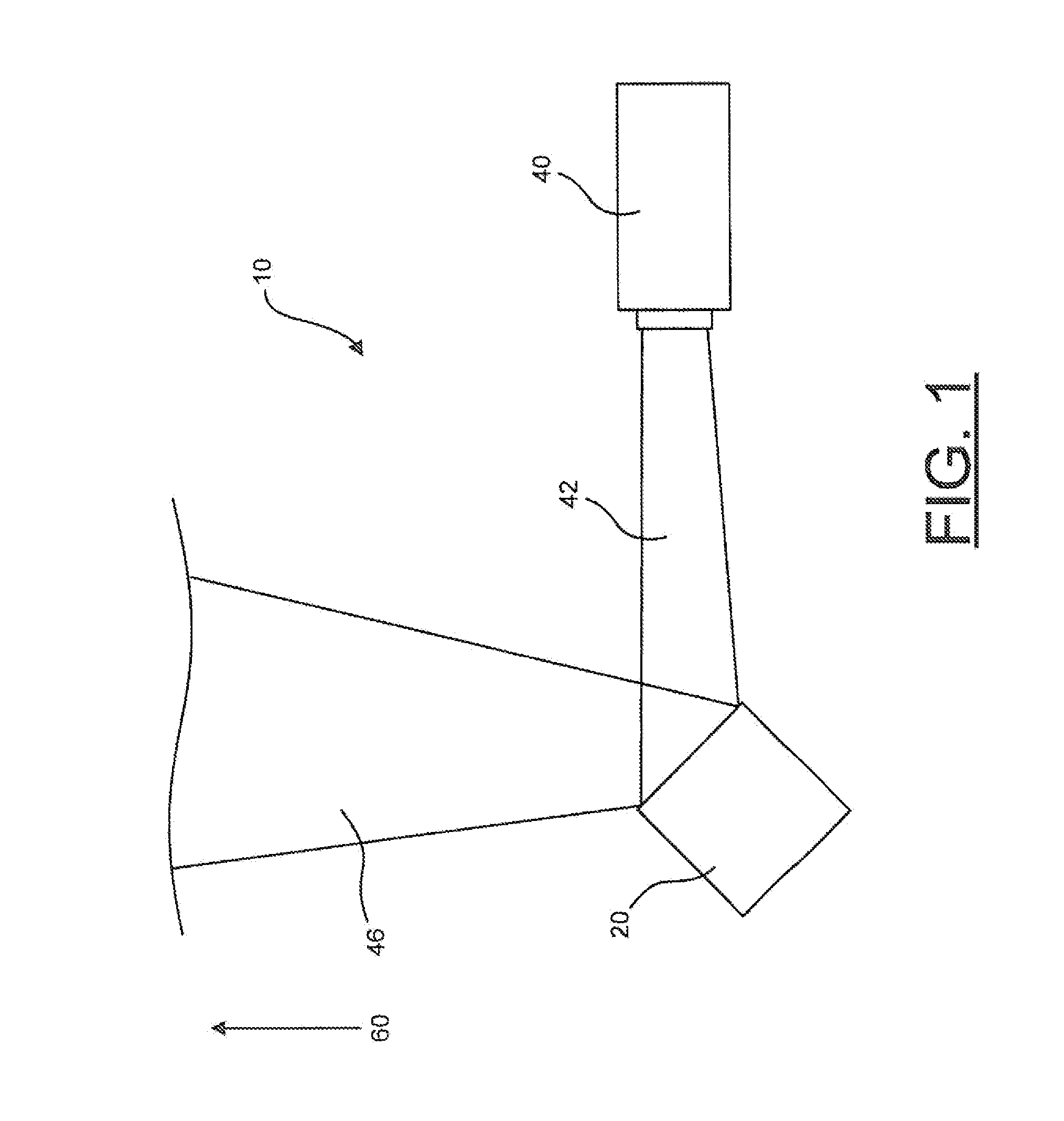
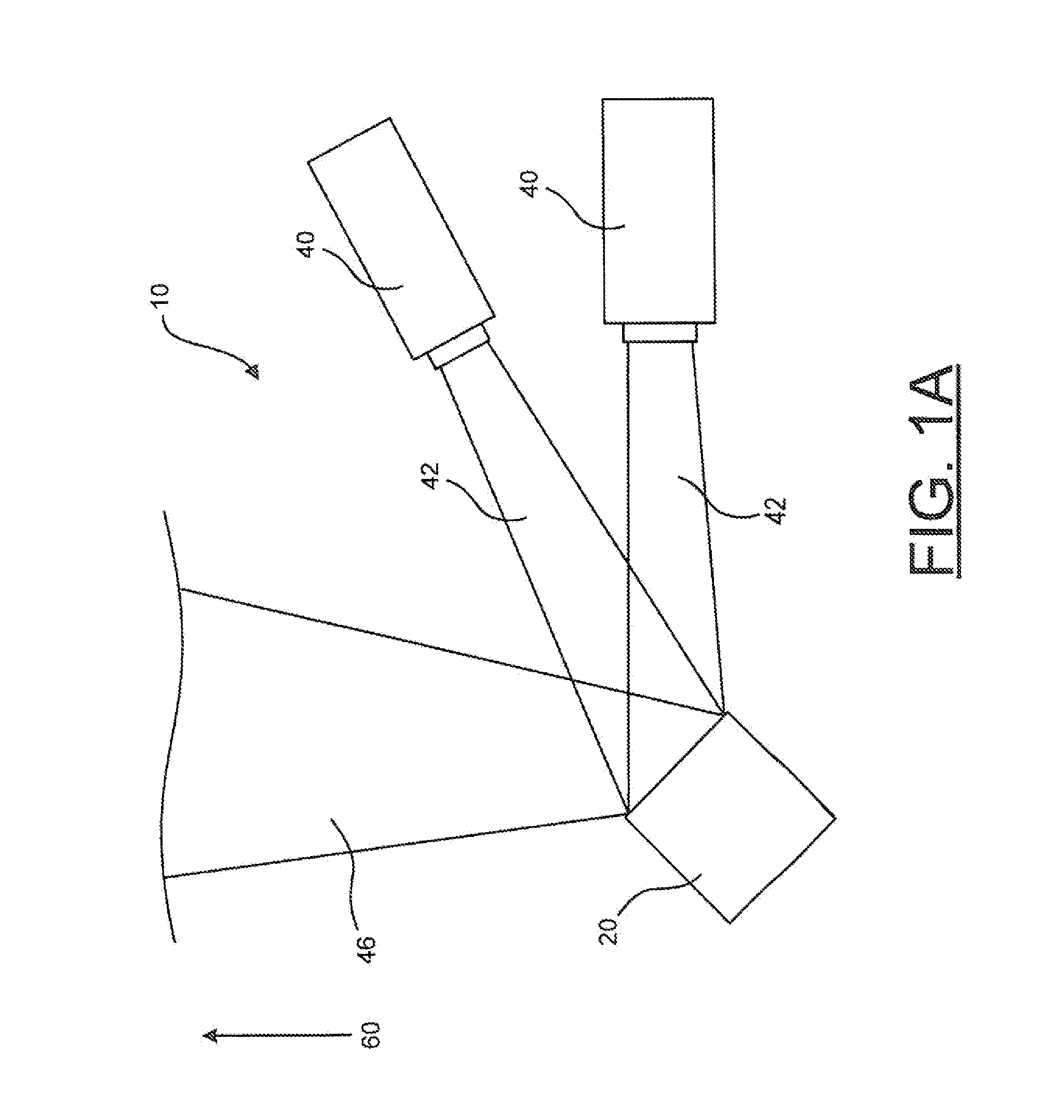
[0012]With the foregoing in mind, the invention is related to a lighting device that may advantageously receive a source light emitted from a light source in one wavelength range and redirect the light to a desired output direction in another wavelength range. The lighting device can also advantageously combine conversion and redirection of the source light in one operation. By providing one lighting device that advantageously combines these operations, the present invention may beneficially possess characteristics of reduced complexity, size, and manufacturing expense.

Problems solved by technology

Conversely, PWM circuits that may be used to control a perceived intensity of light emitting semiconductors must be operable at considerably higher frequencies, or otherwise risk producing visual flicker.

Method used


Image

  • MEMS wavelength converting lighting device and associated methods
  • MEMS wavelength converting lighting device and associated methods
  • MEMS wavelength converting lighting device and associated methods

Examples


Embodiment Construction

[0035]The present invention will now be described more fully hereinafter with reference to the accompanying drawings, in which preferred embodiments of the invention are shown. This invention may, however, be embodied in many different forms and should not be construed as limited to the embodiments set forth herein. Rather, these embodiments are provided so that this disclosure will be thorough and complete, and will fully convey the scope of the invention to those skilled in the art. Those of ordinary skill in the art realize that the following descriptions of the embodiments of the present invention are illustrative and are not intended to be limiting in any way. Other embodiments of the present invention will readily suggest themselves to such skilled persons having the benefit of this disclosure. Like numbers refer to like elements throughout.

[0036]In this detailed description of the present invention, a person skilled in the art should note that directional terms, such as “abov...


PUM


Abstract

A lighting device is described for receiving source light within a predetermined source wavelength range, converting the source light into a converted light, and reflecting the converted light to a desired output direction. The lighting device may use a micro electromechanical system (MEMS) device to receive and redirect the source light to the desired output direction. A conversion coating may be applied to the operative surface of the MEMS device to convert the source light into a converted light.

Description

FIELD OF THE INVENTION[0001]The present invention relates to the field of lighting devices and, more specifically, to applying a conversion coating to a repositionable surface of a MEMS lighting device to direct a light of variable wavelength ranges in a desired output direction.BACKGROUND OF THE INVENTION[0002]Lighting devices that include a conversion coating conveniently allow the conversion of light from a source light source into a light of a different wavelength range. Often, such conversion coatings are created by using a phosphorous coating. These wavelength conversion coatings may sometimes applied to lenses located in line with the light projected from a light source. In some instances the conversion coating may be applied to the light source itself. A number of disclosed inventions exist that describe lighting devices that utilize a conversion coating to convert light with a source wavelength range into light converted wavelength range.[0003]Color-mixing, tunable white li...

Claims


Application Information

Patent Timeline
Patent Type & Authority Patents(United States)
IPC IPC(8): G02B26/00
CPCG02B26/0833G02B26/08H04N9/3194H04N9/3185
Inventor MAXIK, FREDRIC S.SOLER, ROBERT R.BARTINE, DAVID E.ZHOU, RANBASTIEN, VALERIE A.
Owner HEALTHE INC
Learn More