Electrical connector

a technology of electrical connectors and connectors, applied in the direction of coupling contact members, coupling device connections, electrical apparatus, etc., can solve the problems of affecting the size of the magnetic mechanism, the traditional electrical connectors generally fail to meet the requirements of both miniaturization and strong magnetic force, and achieve the effect of enlarging the size of the magnetic block and strengthening the magnetic attraction

Inactive Publication Date: 2013-03-05
CHENG UEI PRECISION IND CO LTD
View PDF7 Cites 20 Cited by
  • Summary
  • Abstract
  • Description
  • Claims
  • Application Information

AI Technical Summary

Benefits of technology

[0006]As described above, the magnetic block is put forward into the receiving space of the insulating housing so as to make use of the inner space of the electrical connector effectively. So, it could be in favor of enlarging the size of the magnetic block so as to reinforce the magnetic attraction between the electrical connector and a mated connector, even though it is under the circumstances of no affecting the miniaturization of the electrical connector.

Problems solved by technology

However, the size of the magnetic mechanism often affects the magnetic force of the magnetic mechanism.
As a result, the traditional electrical connector generally fails to meet the requirements of both miniaturization and strong magnetic force at the same time.

Method used


Image

  • Electrical connector
  • Electrical connector
  • Electrical connector

Examples


Embodiment Construction

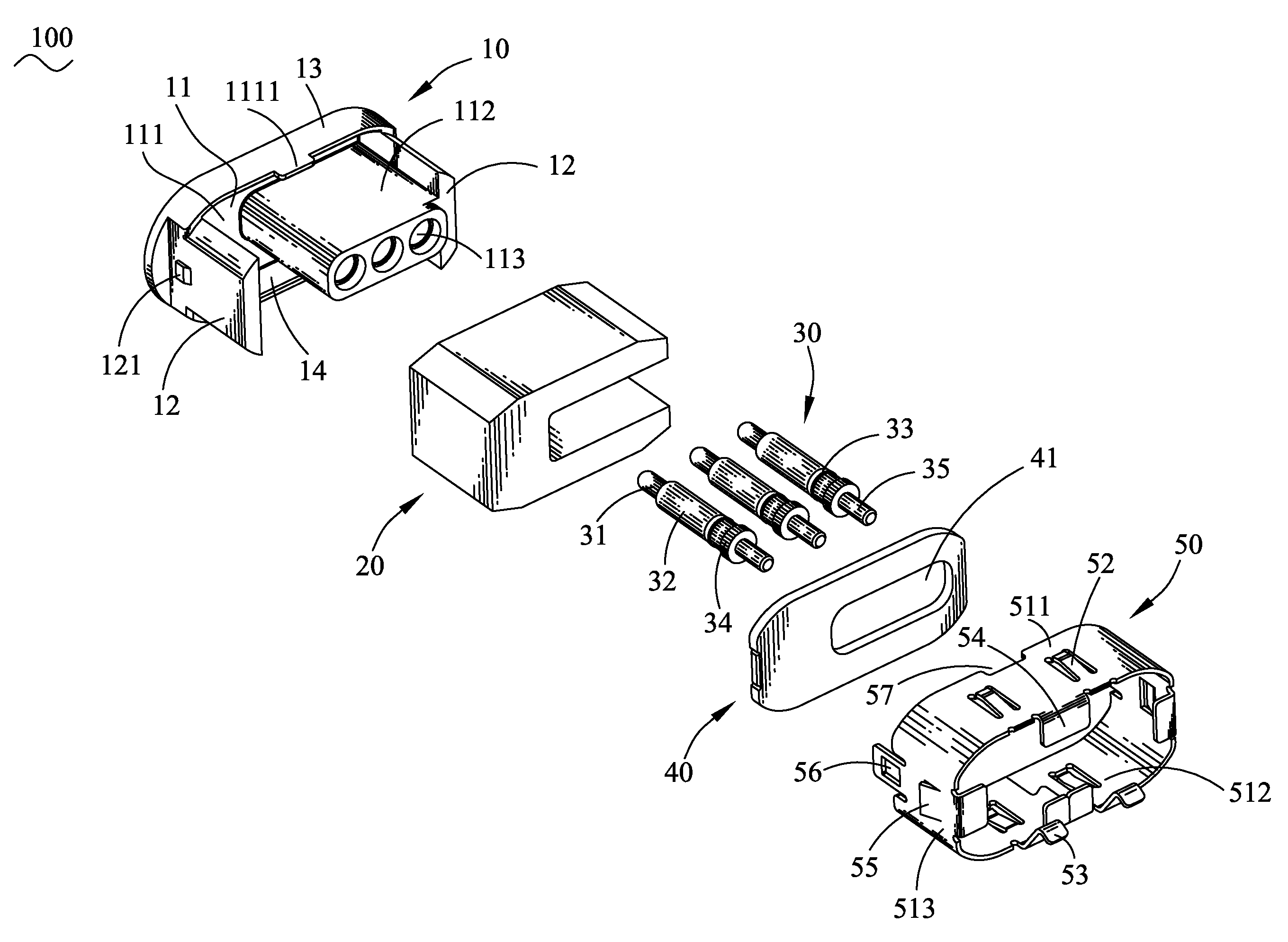
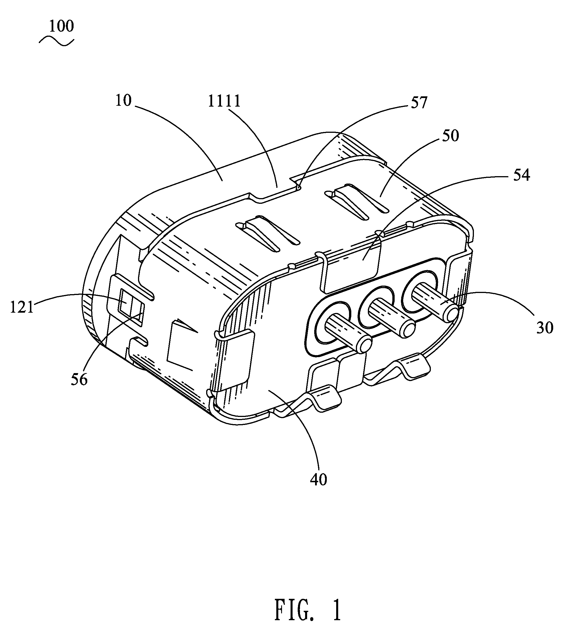
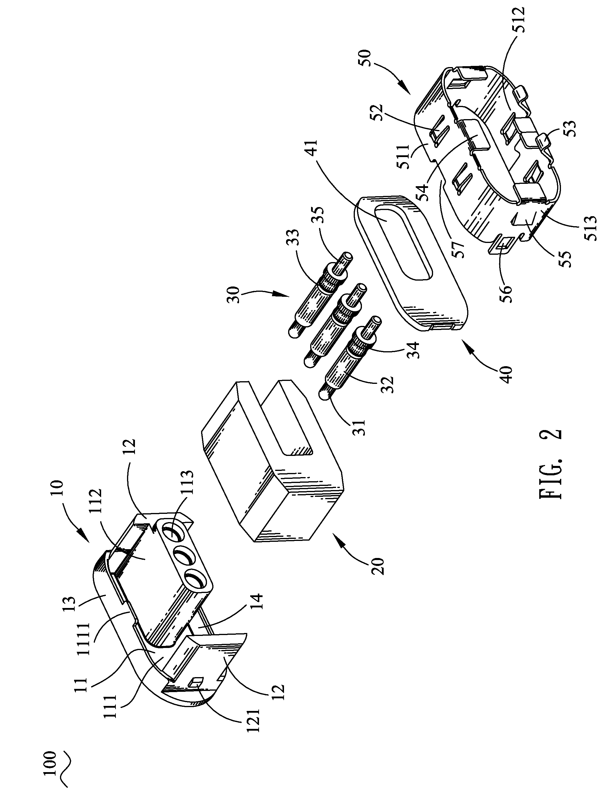
[0011]Referring to FIGS. 1-2, the electrical connector 100 includes an insulating housing 10, a magnetic block 20, a plurality of probe pins 30 assembled in the insulating housing 10, a metal plate 40, and a metal shell 50 enclosing the insulating housing 10.

[0012]With reference to FIGS. 2-3, the insulating housing 10 has a front wall 11 of substantially elliptic shape from a front view. A rear surface of the front wall 11 extends rearward to form a tongue portion 112 having a smaller dimension than the front wall 11. The insulating housing 10 defines a plurality of inserting holes 113 longitudinally penetrating through the front wall 11 and the tongue portion 112. An inner sidewall of the inserting hole 113 has a front portion thereof protruded inward to form a ring-shaped blocking wall 1131, and has a rear portion thereof concaved inward to form a circular blocking groove 1132. The rear surface of the front wall 11 has two opposite ends thereof protruded rearward to form a pair of...


PUM


Abstract

An electrical connector includes an insulating housing having a front wall, a top wall, a bottom wall and two side walls. A rear surface of the front wall extends rearward to form a tongue portion. A receiving space is formed among the front wall, the top wall, the bottom wall and the side walls, wherein the tongue portion is located in the receiving space. A plurality of probe pins is assembled in the insulating housing. A magnetic block has a shape matched with the receiving space and is assembled in the receiving space. A metal plate is placed behind the magnetic block by passing a rear end of the tongue portion therethrough. A metal shell encloses the insulating housing and further electrically resists against a rear side of the metal plate to secure the magnetic block and the metal plate in the insulating housing.

Description

BACKGROUND OF THE INVENTION[0001]1. Field of the Invention[0002]The present invention relates to an electrical connector, and more particularly to an electrical connector adapted to a mated connector by virtue of magnetic attraction.[0003]2. The Related Art[0004]A traditional electrical connector connected with a mated connector by magnetic attraction generally includes an insulating housing, a plurality of probe pins and a magnetic mechanism assembled in the insulating housing respectively. In use, the interconnection between the electrical connector and the mated connector is apt to be influenced by the magnetic force of the magnetic mechanism. However, the size of the magnetic mechanism often affects the magnetic force of the magnetic mechanism. Moreover, the rapid developments of electronic products call for more stringent requirements to miniaturization of the electrical connector. As a result, the traditional electrical connector generally fails to meet the requirements of bot...

Claims


Application Information

Patent Timeline
Patent Type & Authority Patents(United States)
IPC IPC(8): H01R13/60
CPCH01R13/6205H01R13/24H01R13/506
Inventor LIN, JUI-PINLAI, MING-CHUN
Owner CHENG UEI PRECISION IND CO LTD
Why Eureka
Try Eureka