Releasable holding mechanism and method of use

a technology of releasing mechanism and release mechanism, which is applied in the direction of life-saving, vessel safety, accident situation locks, etc., can solve the problems of unintentional or unintentional release of roll bars, power and energy consumption of the release mechanism, and roll bars to either fasten in a lower position or release unintentionally or unfasten, etc., to achieve the effect of fast release and low energy demands

Inactive Publication Date: 2011-01-11
BENTELER AUTOMOBILTECHNIK GMBH +1
View PDF13 Cites 6 Cited by
  • Summary
  • Abstract
  • Description
  • Claims
  • Application Information

AI Technical Summary

Benefits of technology

In accordance with the present invention, there is provided a mechanism that can be operated with a minimum of energy. Further, in automotive applications the release action can be controlled by management systems already available in the vehicle.
The holding mechanism may be situated in a unclean environment and it may be preferable that the releasable holding mechanism comprises a sealed housing that contains the second distal end of the lever, the first magnetic force for preventing movement of the lever in the locked position and the release means comprising the second magnetic force that is useable to oppose the first magnetic force. The housing will protect the contact surfaces of the magnet and the second distal end of the lever and therefore improve the magnetic attraction between the two elements.
Another feature that may improve the magnetic attraction between the second distal end and the magnet is that the lever is preferably formed with a hole through which the pivot extends, the hole being of a diameter that is sufficiently greater than the diameter of the pivot such that the second distal end may self align with the first magnetic force.
The skilled person shall appreciate that the general principle of the present invention may be used for a wide variety of releasable holding mechanisms. However, it is preferable that the holding mechanism comprises a mechanical reduction arrangement for reducing the force that the connecting element applies to the releasable holding mechanism such that the turning force that urges the holding means towards the unlocked position is reduced hence the magnetic force required to prevent movement of the holding means does not have to be so large.
In accordance with the present invention there is achieved one releasable holding mechanism that can be released fast with low energy demands. The releasing action is activated by the movement of a lever, for instance a pivoting lever securing the locking of a connecting member at one distal end. The movement of the lever is balanced between a static holding force provided for instance by a permanent magnet that generates a holding torque, and one opposing releasing force provided for instance by a pre-charged spring, generating a unlocking torque that is lower than said holding torque. In the releasing action, one electromagnet can be energized to act upon the lever with an assisting unlocking torque that together with the pre-charged spring overcomes said holding torque. If the connecting element is pre-tensioned in its release direction or if it affects the torque balance of the lever in other ways, this can be accounted for by introducing an off-center arrangement of the pivot axis of the lever.

Problems solved by technology

The holding mechanism to be used in a roll over protection system faces several problems:Rough environmental conditions such as vibrations, tilting, dust and moisture that can cause the roll bars to either fasten in a lower position or release unintentionally.Tolerances and deflections in the vehicle chassis create positioning problems and might cause the roll bar to release unintentionally or fasten.The power and energy consumption of the release mechanism should be very low to avoid the need for extra power supplies like electrical capacitors.
The main problem is that they are not regenerative and after being used they must be replaced.
This solution is disadvantageous in that a minor tilting of the connection rod leads to movement directly in the release mechanisms locking balls.
As a result the roll bar may be released unintentionally.
The direct connection between the connection rod and the release mechanism requires high power and energy consumption when the actuator releases, because the actuator must work against most of the spring load.

Method used


Image

  • Releasable holding mechanism and method of use
  • Releasable holding mechanism and method of use
  • Releasable holding mechanism and method of use

Examples


Embodiment Construction

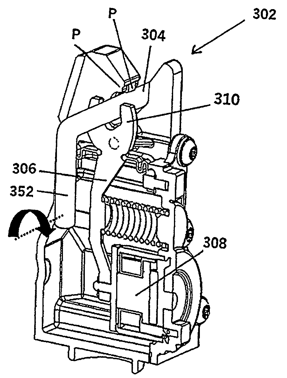
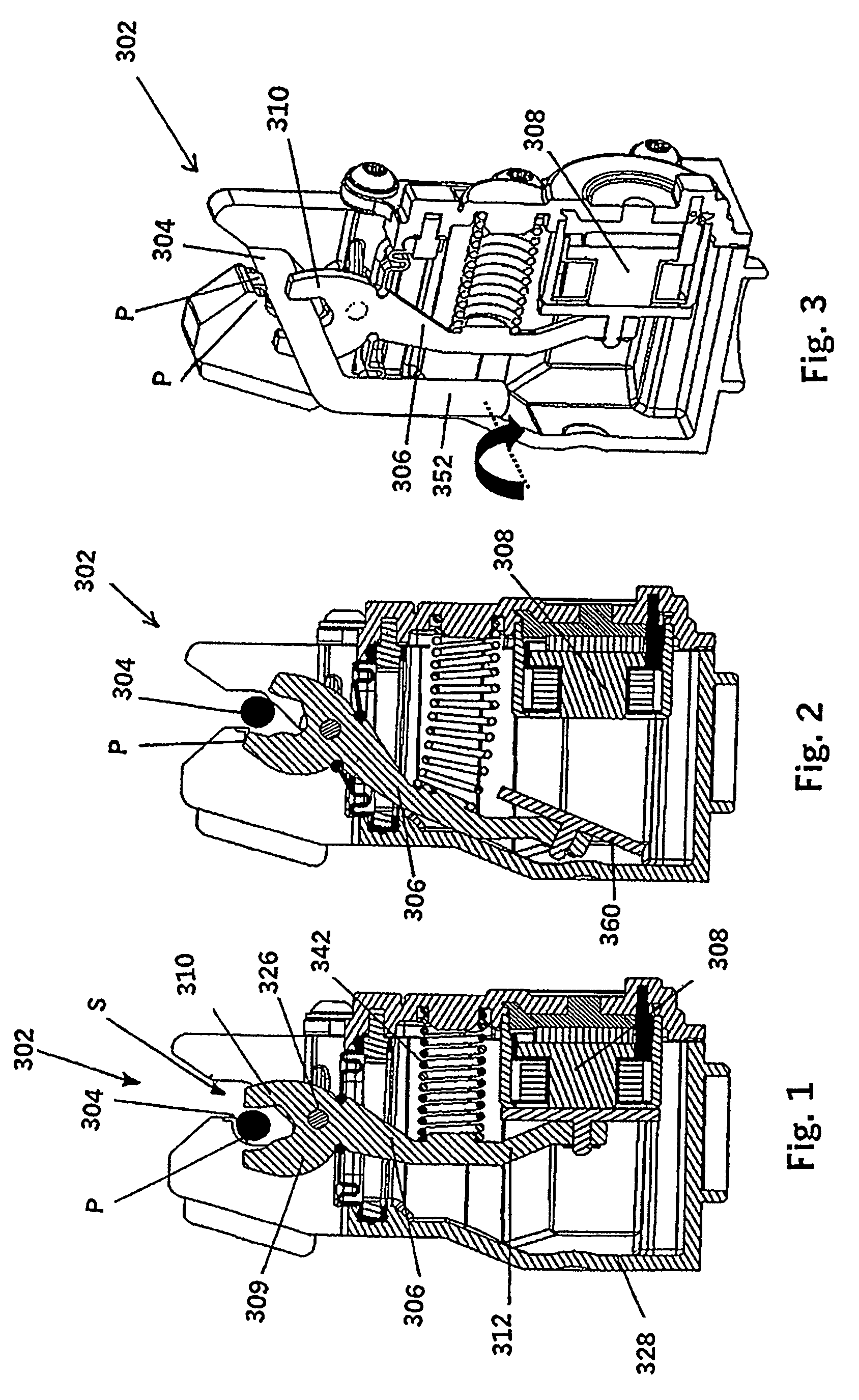
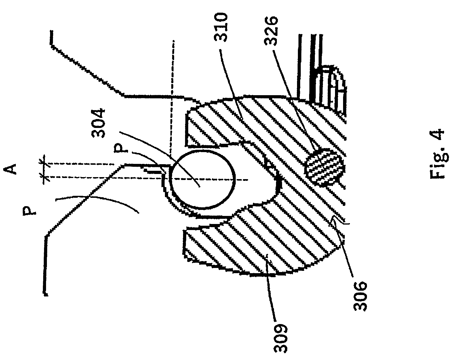
With reference to FIGS. 1-3, there is shown a first embodiment of a releasable holding mechanism 302 for locking and releasing a connecting element 304. The releasable holding mechanism 302 comprises holding means or unit for retaining the connecting element 304 in a locked position in the form of a protrusion P and a pivotable lever 306 with at least one notch 310 and further means for preventing movement of the lever 306 from the locked position (as shown in FIGS. 1 and 3) to an unlocked position (as shown in FIG. 2) (e.g. a release unit) is provided by the attractive magnetic force for instance of a permanent magnet. The lever 306 is capable of being influenced by a magnetic force of said permanent magnet; this magnetic force retains the lever 306 in the locked position. The axis 326 of said pivot is preferably arranged in the same base element or housing as the protrusion P. The releasable holding mechanism 302 comprises a combined magnet unit 308 comprising a permanent magnet a...


PUM


Abstract

The invention relates to a releasable holding mechanism which may be used to hold and release a roll bar in a roll over protection system. The roll bar is often made part of the seat structure of vehicle, or a part of the chassis of the vehicle. The releasable holding mechanism will be fastened rigidly or slightly loose to the roll bar frame, seat frame or the chassis of the vehicle. Between the roll bar and the releasable holding mechanism there will be a connection element that is rigidly or slightly loosely fastened to the roll bar. The arrangement of fastening the connection element rigidly or slightly loosely depends on the tolerances for positioning the actuator towards the roll bar. The connection element is locked or released by the releasable holding mechanism. The releasable holding mechanism is locked / -engaged when the roll bar is pushed downwards whereby the connection element is forced into the releasable holding mechanism. The releasable holding mechanism is to release the connecting element when a signal is sent to the release element of the holding mechanism. The releasable holding mechanism can be activated by one short duration pulse, for instance a pulse from an electronic control unit for activation of airbags in a vehicle. The system can be activated with low energy demands.

Description

BACKGROUND OF THE INVENTIONI. Field of the InventionThe present invention relates to a releasable holding mechanism with means for retaining the mechanism in a locked condition and to a method for actuating the mechanism, and is concerned particularly, although not exclusively, with a releasable holding mechanism for use in automotive roll-over protection systems (ROPS), releasable headrest, backrest, raisable hood for pedestrian protection and other automotive applications.The invention is designed especially for ROPS, but it may be applied otherwise where there is a need for releasing a secured load, e.g. safety systems at sea, life rafts (as an alternative to rope-cutter devices), securing and releasing cargo, and release mechanisms for aero / space, etc.II. Description of the Related ArtThe Roll Over Protection System (ROPS) is installed in a vehicle to protect the driver and passengers if the vehicle should roll over. During normal driving the roll over bar or the protection memb...

Claims


Application Information

Patent Timeline
Patent Type & Authority Patents(United States)
IPC IPC(8): B60R21/13E05B47/00B60R21/34B60R21/38
CPCB60N2/4885B60R21/13B63C9/22E05B77/08B60R21/38B60R2021/135Y10T70/7057B60N2/888
Inventor NORUM, VIGGO L.VESTGARD, BARDOYEN, JANGRONLI, OIVINDJENSSEN, GEORG B.PEDERSEN, ROALD HELLAND
Owner BENTELER AUTOMOBILTECHNIK GMBH
Why Eureka
Try Eureka