Electromagnetic valve

A solenoid valve and magnetic attraction technology, which is applied in the field of solenoid valves, can solve the problems of increasing the diameter of the coil and increasing the size of the solenoid valve, and achieve the effect of increasing the magnetic attraction force and improving the operation response

Inactive Publication Date: 2007-03-21
AISIN SEIKI KK
View PDF1 Cites 6 Cited by
  • Summary
  • Abstract
  • Description
  • Claims
  • Application Information

AI Technical Summary

Problems solved by technology

However, an increase in core diameter results in an increase in coil diameter, thereby increasing the size of the solenoid valve itself

Method used


Image

  • Electromagnetic valve

Examples


Embodiment Construction

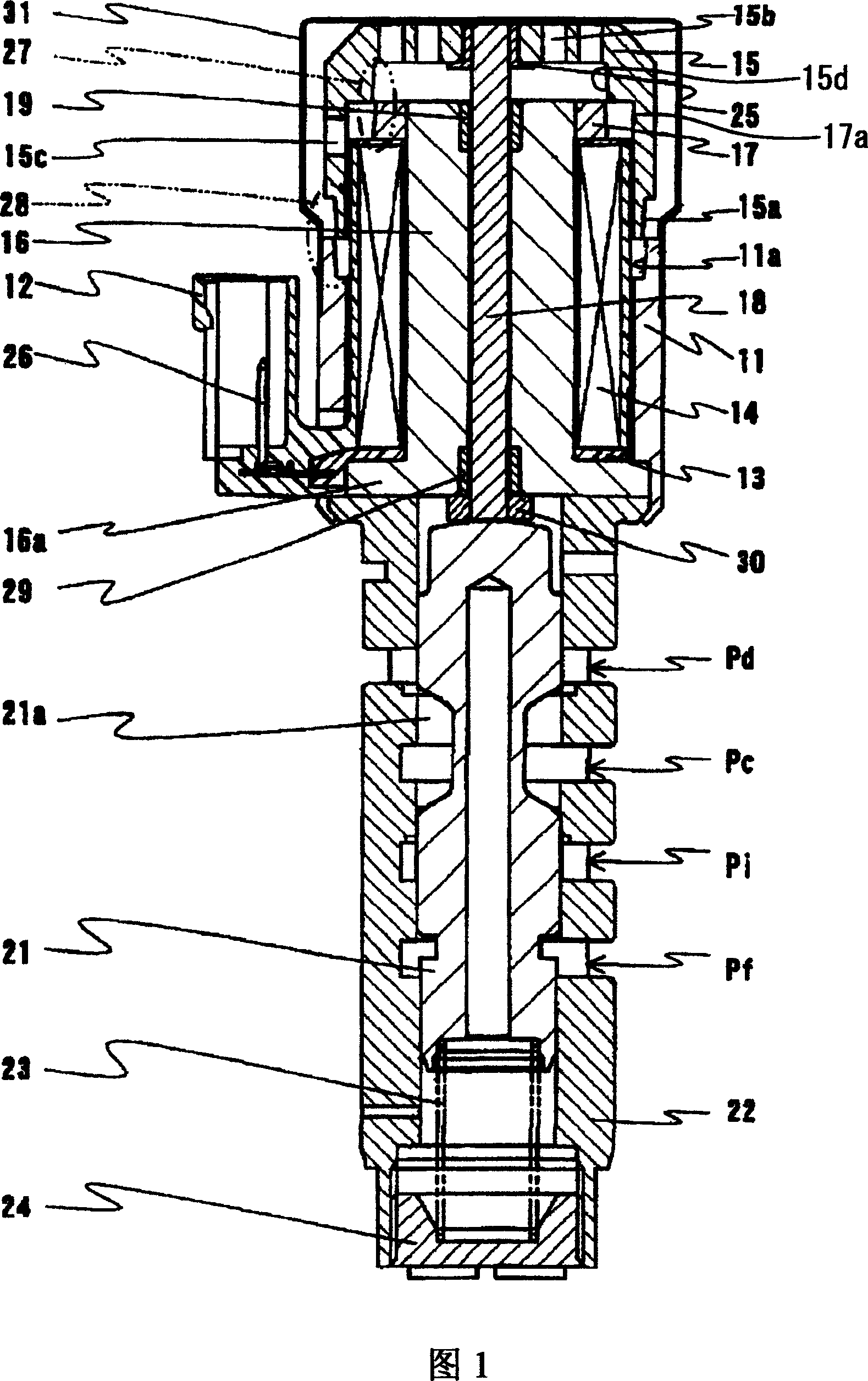
[0010] An embodiment of the present invention will be described below with reference to the accompanying drawings. A solenoid valve according to an embodiment of the present invention is shown in FIG. 1 . According to this embodiment, the solenoid valve is correspondingly a linear solenoid valve for a hydraulic control device which can realize feedback control.

[0011] As shown in FIG. 1 , a coil 14 wound on a bobbin 13 made of resin is housed in a case 11 . A connector 12 made of resin is fixed to the first end of the housing 11 . The connector 12 is electrically connected to the coil 14 and is integral with a terminal 26 for energizing the coil 14 . A stepped magnetic attraction portion 11 a whose wall becomes thinner is formed at the second end of the housing 11 .

[0012] A cylindrical front end yoke (ie, serving as a fixed iron core) 16 is built in the bobbin 13 and has a flange 16a at its first end on the terminal 26 side. An annular rear end yoke 17 is integrally p...


PUM


Abstract

A solenoid valve includes a cylindrical bobbin provided with a coil thereon, a fixed core provided through an inner periphery of the bobbin, a case provided at an outer periphery of the bobbin, the case housing the fixed core, a plunger provided facing the fixed core and being movable by a magnetic attractive force, a shaft member extended to penetrate through the fixed core, the shaft member having a first end provided with the plunger in a way that the plunger is movable integrally with the shaft member, a valve member contacting a second end of the shaft member and driven by the shaft member, a biasing member biasing the valve member, the shaft member and the plunger in a counter direction of a moving direction by the magnetic attractive force, and a plurality of magnetically attracting portions provided at the plunger.

Description

technical field [0001] The invention relates to a solenoid valve for a fluid circuit. Background technique [0002] Known solenoid valves include a plunger made of iron-based material and driven by an electromagnetic coil, and a valve core member that is biased by a spring and contacts the plunger via a shaft (for example, Japanese Patent Document JP09- 053742A). According to the known solenoid valve described in Japanese Patent Document JP09-053742A, the spool (13) slidably embedded in the sleeve (11) is in contact at one end thereof with the plunger (4) via the shaft (40). A return spring exerting a biasing force on the valve core is supported at the other end of the valve core by means of a screw plug (15). [0003] The magnetic attraction part is formed by a plunger and a fixed iron core (2). The magnetic attraction force is mainly determined by the outer diameter of the fixed iron core. In order to increase the magnetic attraction force, the amount of excitation cur...

Claims


Application Information

Patent Timeline
Patent Type & Authority Applications(China)
IPC IPC(8): F16K11/07F16K31/06
CPCF16K31/061F15B13/0442
Inventor 上舘芳信大须贺晋
Owner AISIN SEIKI KK
Why Eureka
Try Eureka