Accordingly, modern cold-storage appliances such as refrigerators and freezers are usually compartmentalised, albeit not often effectively, so that a user can store different types of food in different compartments.
That rush of
ambient air into the cabinet causes its
internal temperature to rise, hence consuming more energy in redressing that rise by running the cooler unit.
The incoming
ambient air introduces the possibility of airborne
contamination, and
moisture in that air also gives rise to condensation and ice within the cabinet.
The more often and frequently the cabinet is opened, as may happen especially in commercial
cold storage appliances, the worse these problems get.
In upright-door arrangements, the limitations of the vertical seal mean that loss of
cold air and induction of warm air can even occur when the door is closed.
Such a chest freezer is inconvenient and wasteful of space because it precludes use of the space immediately above the freezer, which space must be preserved to allow its lid to be opened.
Even if a sliding lid is used instead of an upwardly-opening lid, items cannot be left conveniently on top of the lid.
It is also well known that large chest freezers can make access to their contents extremely difficult, it being necessary to stoop down and shift numerous heavy and painfully cold items to get to items at the bottom of the freezer compartment
In typical cold-storage appliances, segregation of food is compromised by the
convection and / or forced-air principles on which those appliances rely.
The substantially open baskets or shelves designed to promote convective circulation of air between the compartments also promote the circulation of
moisture, enzymes and harmful
bacteria In addition, any liquid that may spill or leak, such as juices running from uncooked meats, will not be contained by the open baskets or shelves.
Although only one drawer need be opened at a time, the apertures in the bottom allow
cold air to flow freely from the open drawer, which is replaced by warm moist
ambient air to the detriment of energy efficiency and with the increased possibility of cross-
contamination.
Even when closed, the accumulation of
cold air towards the bottom of the cabinet will exert increased pressure on the vertical seals of the lowest drawers, increasing the likelihood of leakage if the seal is faulty.
Whilst this will impede the passage of air into and out of the drawer, it will not form an impervious seal.
As this is not a vapour seal,
icing and cross-
contamination is likely to occur even when the drawer is closed.
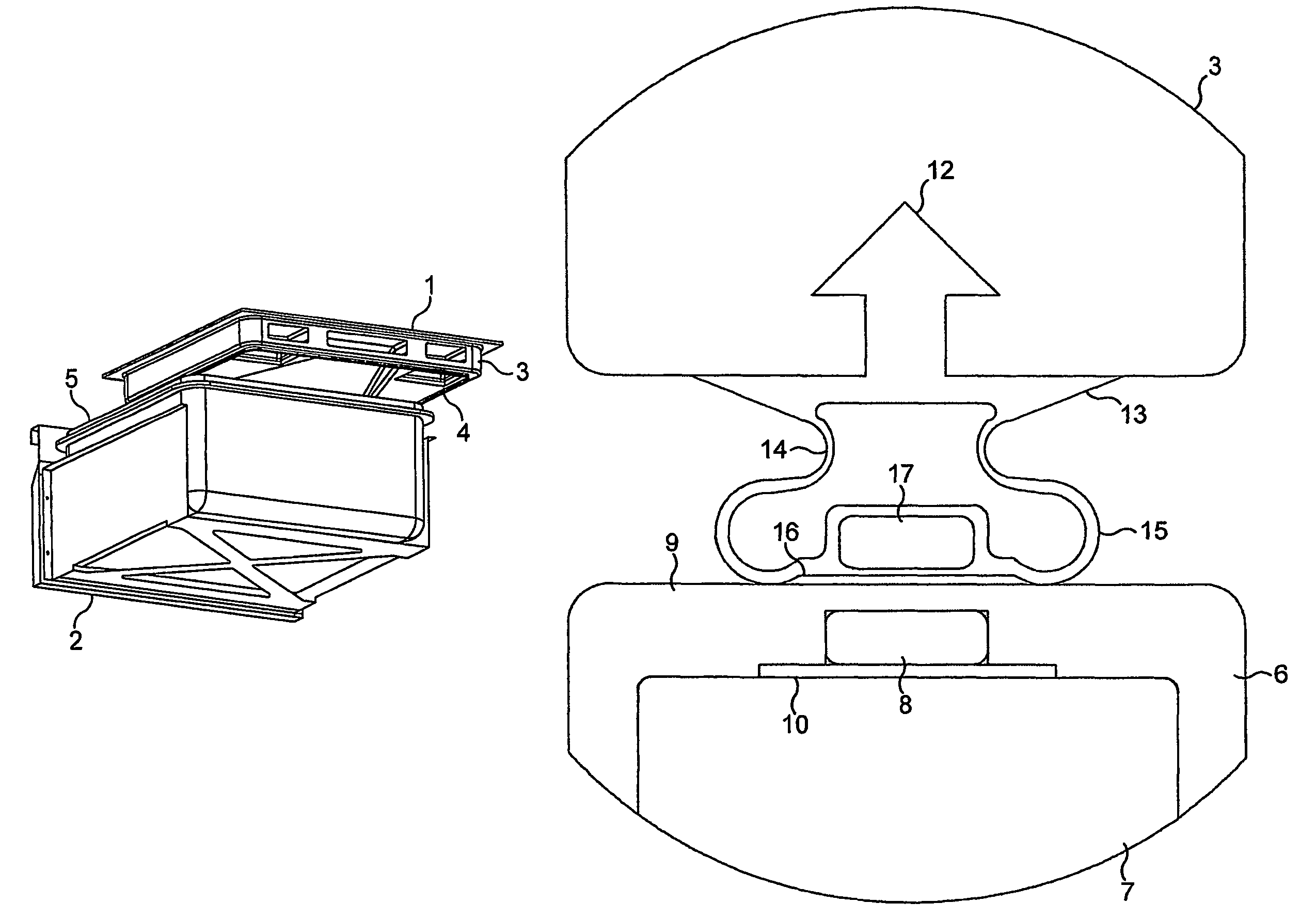
The Applicant has appreciated a
disadvantage in this arrangement, namely that as the freezer drawer resides within the cooled interior when closed, the outer surfaces of the drawer within the cabinet will be cooled to the temperature of the refrigerator.
Accordingly, when the drawer is opened, those cooled outer surfaces will be exposed to ambient air containing
moisture that will condense on the cooled surfaces leading to an undesirable accumulation of moisture.
Condensation involves transfer of
latent heat from water vapour to the drawer, thus increasing the burden of cooling the drawer again when the drawer is returned to the closed position within the cabinet.
A further
disadvantage of introducing water into the interior of the refrigerator is that it may freeze: this can be a particular problem where the drawer of the enclosed compartment meets the insulated top, as any
ice formation will form a seal that locks the drawer in a permanently closed position.
This
disadvantage was appreciated by Earle, as a
cam mechanism is mentioned in GB 602,329 to break any ice formed at the seals or on the runners or other support surfaces of the drawers.
Of course, the accumulation of ice on
moving parts of the drawer mechanism is also undesirable as it will impede movement of the drawer.
However, there has to be a gap left between the drawer and the refrigerating unit if the drawer is going to open.
If a larger gap is tried instead, there will be a greater
spillage of air and hence the refrigerator will be less energy-efficient and more susceptible to cross-contamination.
That aside, the
spillage of cold air in Ewen lowers the temperature within the cabinet around the drawers, and so increases the likelihood of condensation on the drawers when opened.
Also, the internal divisions between the drawers do not allow for ambient
heat transfer to the drawers but only for
heat transfer between the drawers, thus promoting drawer-to-drawer temperature equalisation over time.
Left for long periods, or even overnight, large parts of the external surface of each drawer will fall to temperatures significantly below ambient
dew point Condensation or ice will therefore form on those surfaces as soon as the drawers are opened; similarly, if the drawers are removed and left outside the appliance, they will start to ‘sweat’ with condensation.
An over-sized cabinet would reduce the
piston effect but would also be wasteful of space.
Whilst Ewen speaks of different temperatures in different drawers, the plurality of cooling lids are connected in series and have no means for individual
temperature control in each drawer.
The different temperatures are designed-in by providing some drawers with more cooling elements than others, but there is no measurement or control of those temperatures in use.
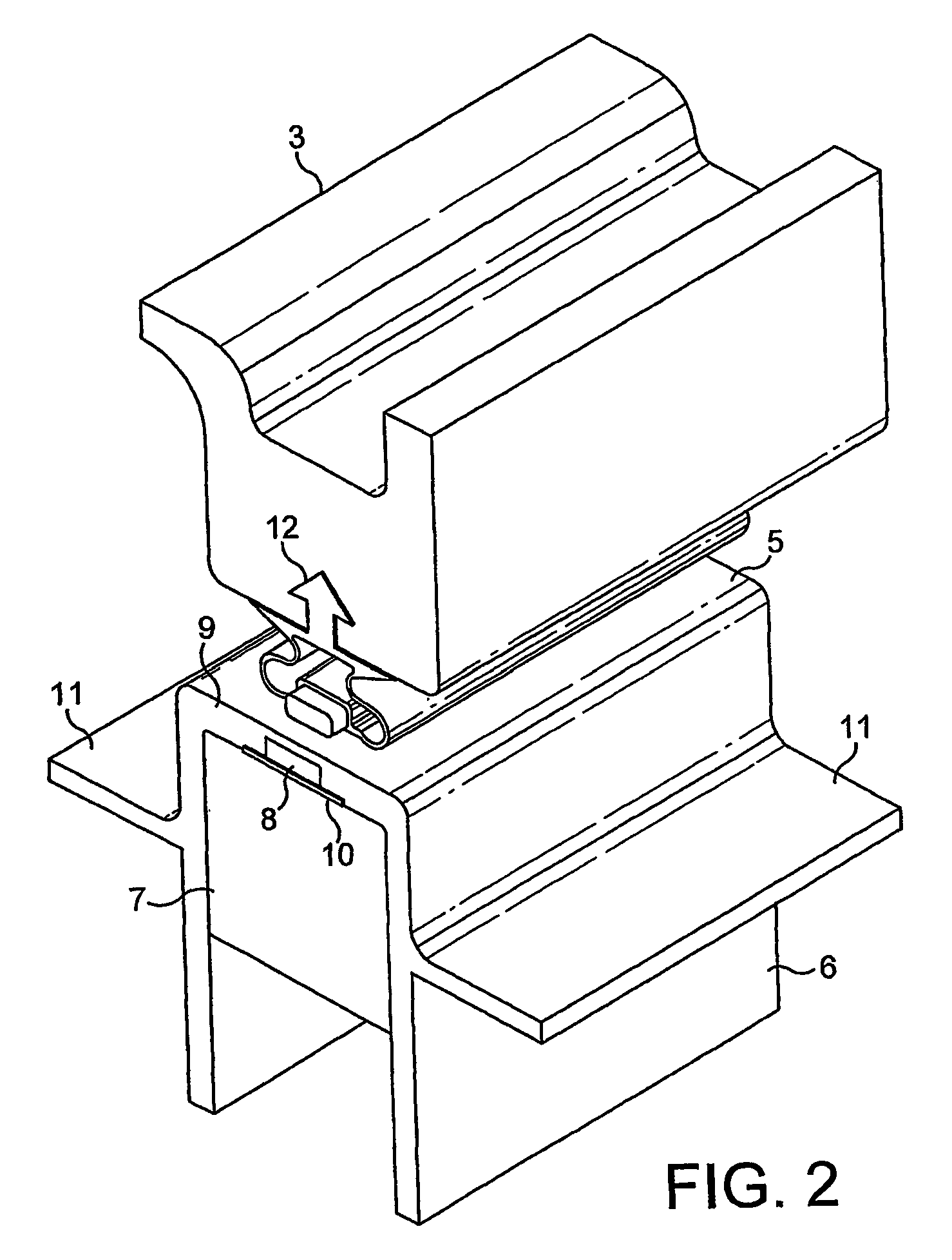
It is well known that existing magnetic seals are designed to be pushed together and pulled apart, which characteristic is not appropriate for sealing to a lid around the upper periphery of a drawer.
Typical resilient magnetic seals would be expected to deform and wear unacceptably if used in such circumstances, and to present excessive
frictional resistance to movement of the drawer.

