Surveillance camera apparatus and surveillance camera system

a surveillance camera and camera system technology, applied in the field of surveillance camera equipment and surveillance camera system, can solve the problems of inability to unmanned apparatus, lack of reliability of obtained tracking information, and difficulty in visually identifying the image of moving objects, and achieve the effect of accurate control of optical axes

Active Publication Date: 2013-03-05
FUJIFILM CORP
View PDF16 Cites 13 Cited by
  • Summary
  • Abstract
  • Description
  • Claims
  • Application Information

AI Technical Summary

Benefits of technology

[0013]Also, it is preferable that the wide-angle camera comprises plural kinds of stationary cameras, which have different focal lengths, focus on longer distances as the focal lengths are longer and have image-capturing ranges substantially equivalent to each other. A near-side of a depth of field of one stationary camera may overlap a far-side of a depth of field of another stationary camera, whose focused position is adjacent to that of the one stationary camera. Thereby, it is possible to capture over the substantial entire image-capturing range with focusing a subject. In addition, at least one of the stationary cameras may include a combination of a plurality of camera modules, which have angles of view equal to each other, have focal lengths equal to each other and are arranged so that directions of capturing optical axes are different from each other. The camera modules individually may capture areas, which are defined by dividing the image-capturing range equally. Thereby, an image of a moving object under surveillance can be captured more larger and more clearly.
[0015]When a moving object to be watched is identified based on an image captured by a wide-angle camera, the posture of a telephotographic camera is controlled so that its optical axis is aimed at the moving object. Thus, the moving object is captured in the center of the image-capturing range of the telephotographic camera. After that, the posture of the telephotographic camera is controlled by feedback control so that the image of the moving object is placed in the center of the image-capturing range of the telephotographic camera. It is therefore possible to capture the moving object continuously while tracking the moving object accurately. When a variable magnification function is provided for a lens of the telephotographic camera, the magnification of the telephotographic camera may be changed in accordance with the size of the image of the moving object contained within the image-capturing range of the telephotographic camera. It is therefore possible to capture the moving object with a suitable size.
[0016]If the view angle of the wide-angle camera is made too wide in order to expand the range where the wide-angle camera can capture, an image captured by the wide-angle camera will be smaller. Therefore, in an advantageous embodiment, a range to be captured may be divided into divisions, and a wide-angle camera is assigned to each division. Further, if plural kinds of stationary cameras, which have different focal lengths, focus on longer distances as the focal lengths are longer and have image-capturing ranges substantially equivalent to each other, are used as the wide-angle camera, when a moving object, which is a surveillance target, appears, the respective stationary cameras can capture the moving object with the substantially the same magnification ratio. Therefore, Not only it is easy to perform image recognition, but also it is easy to observe the moving object on the monitor. If a near-side of a depth of field of one stationary camera overlaps a far-side of a depth of field of another stationary camera, whose focused position is adjacent to that of the one stationary camera, any of the stationary cameras can capture the moving object clearly irrespective of the camera-to-subject distance. Also, it is advantageous to obtain an orientation direction of the telephotographic camera.

Problems solved by technology

It is therefore very difficult to identify the image of the moving object visually as in the apparatus disclosed in JP Hei. 9-55930.
Further, the apparatus of JP Hei. 9-55930 requires manual operation for changing over to the zoom camera, so that the apparatus cannot be unmanned.
Even if the tracking information is obtained based on such a small image captured by the wide-angle camera, the obtained tracking information would lack reliability.
It is therefore difficult to accurately control the optical axis of the zoom camera having a narrow view angle.
Once tracking is ceased, it is very difficult to resume the tracking.
It is therefore impossible to obtain a sufficient effect of surveillance.

Method used


Image

  • Surveillance camera apparatus and surveillance camera system
  • Surveillance camera apparatus and surveillance camera system
  • Surveillance camera apparatus and surveillance camera system

Examples


Embodiment Construction

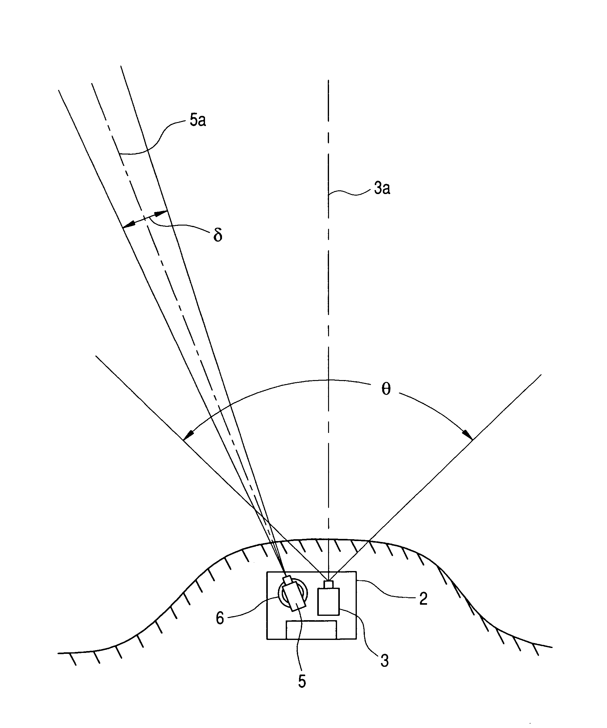
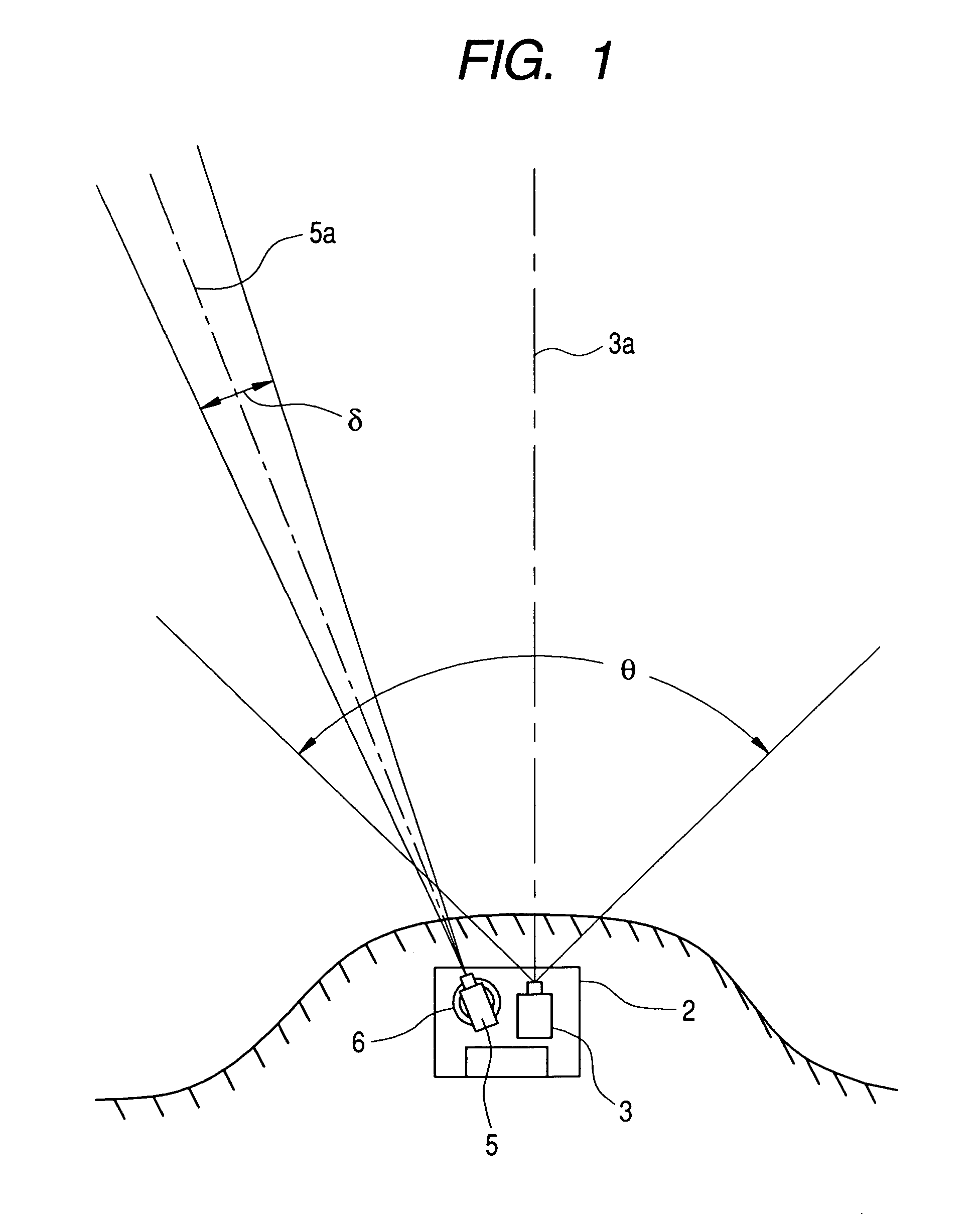
[0028]A surveillance camera apparatus according to an embodiment of the invention has a configuration as schematically shown in FIG. 1. That is, the surveillance camera apparatus is configured so that a wide-angle camera 3 and a telephotographic camera 5 are installed on a base 2 installed, for example, at the tip of a cape. A optical axis 3a of the wide-angle camera 3 is fixedly directed in a constant direction. On the other hand, the telephotographic camera 5 is movably supported by a motor-driven pedestal (posture control unit) 6 provided between the telephotographic camera 5 and the base 2. Thus, an optical axis 5a of the telephotographic camera 5 can be inclined in a panning direction and a tilt direction.

[0029]The surveillance area of this surveillance camera apparatus depends on the angle θ of view of the wide-angle camera 3. The angle with which the telephotographic camera 5 can pan has a range large enough to cover at least the angle θ of view of the wide-angle camera 3 aro...


PUM


Abstract

A wide-angle camera is fixed to direct an optical axis in a fixed direction. A telephotographic camera can be inclined in panning and tilting directions to change an aiming direction of its optical axis. An image signal from the wide-angle camera is evaluated. When an image of a moving object is identified in a frame captured by the wide-angle camera, directivity information corresponding to a position of the moving object is calculated based on a relative position to the center of the frame. In accordance with the directivity information, posture of the telephotographic camera is controlled to aim its optical axis at the moving object. Thereafter, the posture of the telephotographic camera is controlled continuously to place the image of the moving object in the center of the frame captured by the telephotographic camera. The telephotographic camera captures the moving object while tracking it.

Description

BACKGROUND OF THE INVENTION[0001]1. Technical Field[0002]The invention relates to a surveillance camera apparatus and a surveillance camera system, which use plural kinds of cameras in combination so as to clearly capture an image of a moving object, which is a surveillance target within a wide surveillance area.[0003]2. Description of Related Art[0004]A surveillance camera apparatus for security on a coastland or a borderland is required to have a wide surveillance area. In this case, a camera-to-subject distance to be kept under surveillance reaches several kilometers to 10 or more kilometers. Also, it is desired that a surveillance camera apparatus for surveiling a road such as a general road and a highway has a camera-to-subject distance at least several tens to several hundreds meters. It is necessary that such a surveillance camera apparatus has a function of identifying a moving object, which is regarded as a surveillance target, in an early stage and a function of surveiling...

Claims


Application Information

Patent Timeline
Patent Type & Authority Patents(United States)
IPC IPC(8): H04N7/18H04N5/225H04N5/232
CPCG08B13/19602G08B13/19608G08B13/19628G08B13/1963G08B13/19643G08B13/19673H04N5/232H04N7/181H04N23/50H04N23/695
Inventor TANAKA, YASUNORI
Owner FUJIFILM CORP
Why Eureka
Try Eureka