Antenna with shared sources and process for manufacturing multi-beam antenna with shared sources

一种多波束、馈源的技术,应用在卫星远程通信领域,能够解决强像差等问题

Inactive Publication Date: 2010-06-23
THALES SA
View PDF4 Cites 12 Cited by
  • Summary
  • Abstract
  • Description
  • Claims
  • Application Information

AI Technical Summary

Problems solved by technology

These configurations enable the use of compact antennas with low F / D ratios, F being the focal length and D being the diameter of the reflector, and these structures may make the beam compact but give strong aberration

Method used


Image

  • Antenna with shared sources and process for manufacturing multi-beam antenna with shared sources
  • Antenna with shared sources and process for manufacturing multi-beam antenna with shared sources
  • Antenna with shared sources and process for manufacturing multi-beam antenna with shared sources

Examples


Embodiment Construction

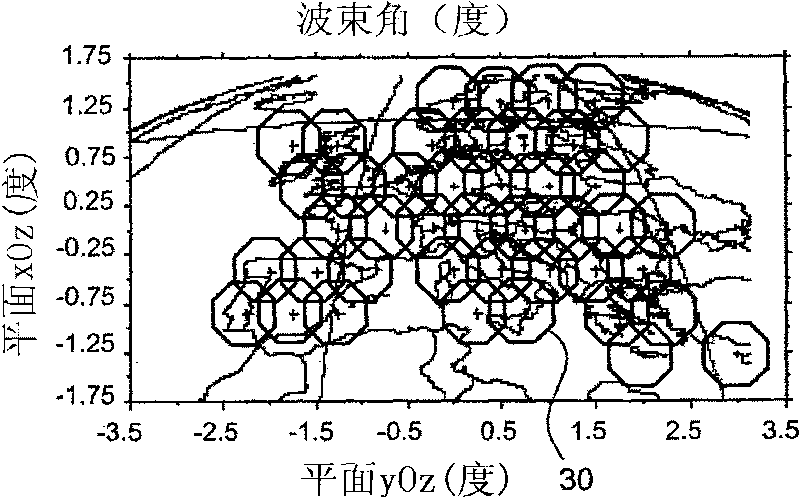
[0035] The antenna structure according to the invention must allow the transmission of information to terminals of very small size. The size of the target terminal dictates the values ​​that the antenna parameters must have, such as the ratio G / T of gain and noise temperature, called the figure of merit, and the equivalent isotropic radiated power (EIRP). For a given geographical coverage and a given frequency, the G / T parameter directly depends on the number of beams to be generated. Therefore, a fixed frequency band and G / T value has a corresponding number of beams and required beam size to produce a given coverage. figure 1 An example of the coverage obtained with a configuration of 43 spots 30 corresponding to a beam angle θ equal to 0.5° is shown. To produce optimal coverage, all points must be contiguous, or even interleaved, and the gain of the antenna must be optimized to correspond to each intersection between three points in the case of a triangular or hexagonal gri...


PUM


Abstract

The invention discloses an antenna with shared sources and process for manufacturing the multi-beam antenna with shared sources, comprising a plurality of same elementary feed sources spaced at the same pitch (P), characterized in that separate feed sources (1-10) in an identical sub-network surrounding a central elementary feed source (7, 5) are associated, Each sub-network (1-7, 4-10) synthesizes a beam, the elementary sources of each sub-network are coupled between them by electromagnetic coupling, The successive sub-networks (1-7, 4-10) comprise at least a common elementary source (4, 5, 6,7), and are shifted from a distance corresponding to a predetermined number of the pitch (P) higher than or equal to one. The invention is in particular used in the field of satellite remote communication.

Description

technical field [0001] The invention relates to an antenna with a shared feed and a method of manufacturing an antenna with a shared feed for generating multiple beams. The invention is particularly applicable to the field of satellite telecommunication. Background technique [0002] In the field of satellite telecommunications, the needs of operators are shifting towards smaller and smaller terminals, A4 or A5 sized terminals, or PDA (Personal Digital Assistant) type terminals or phones to cater for roaming users. [0003] Many applications also involve the trend of using the Internet or higher bit rate applications in existing systems. [0004] To accomplish these tasks, antenna configurations have become increasingly complex, consisting of a large number of feeds associated with many amplifiers to ensure generation of on the order of hundreds or thousands of increasingly narrow beams and provide continent-wide or world-wide coverage . The beams are formed with digital ...

Claims


Application Information

Patent Timeline
Patent Type & Authority Applications(China)
IPC IPC(8): H01Q19/17H01Q3/26
CPCH01Q19/17H01Q1/28H01Q21/0006H01Q21/065H04B7/18515Y10T29/49016H01Q3/26H01Q19/00
Inventor G·拉格内
Owner THALES SA
Why Eureka
Try Eureka