Electrode array

a technology of arrays and electrodes, applied in the field of electrodes, can solve the problems of unsuitability for use, affecting the quality and duration of recordings that can be obtained, and recording is highly susceptible to noise and artifacts

Active Publication Date: 2013-03-05
BRAINSCOPE SPV LLC
View PDF11 Cites 19 Cited by
  • Summary
  • Abstract
  • Description
  • Claims
  • Application Information

AI Technical Summary

Problems solved by technology

With all types of electrodes, a key factor in obtaining accurate and relatively noiseless bio-potential recordings is maintaining adequate contact between the electrode and the skin, because bio-potentials are typically relatively small, i.e. less than about 20 mV, and the recordings are highly susceptible to noise and artifacts.
These types of electrodes are unsuitable for use in areas with much hair, such as on the scalp, and generally provide electrical contact that is not very robust or long lasting, which affects the quality and duration of recordings that can be obtained.
Needle-type electrodes generally provide better and more long-lasting contact, and can be used on the scalp, but involves tedious, uncomfortable and costly procedure to secure contact.
Headband-type electrode connectors are typically used for recording signals from the frontal areas of the brain, and are less useful for recording from other areas of the brain because of the relatively poor signal quality that results.
In addition, headband connectors still require careful skin preparation.
Known electrode apparatus and connectors are therefore limited by being annoying or uncomfortable for the subject, especially when placed on the head.
With the additionally requirement of setting up a stimuli delivery system, the task can quickly become unduly complicated and time consuming.
The discomfort or apprehension associated with the setup is a particular problem for children, infants, and uncooperative subjects.
Interference by an uncooperative subject with the placement and contact of head electrodes can render recordings of evoked brain potentials impossible to obtain or useless because of minimal or inadequate contact.

Method used


Image

  • Electrode array
  • Electrode array
  • Electrode array

Examples


Embodiment Construction

[0022]The following detailed description illustrates the invention by way of example and not by way of limitation. The description enables one skilled in the art to make and use the invention, and describes several embodiments, adaptations, variations, alternatives, and uses of the invention, including what is presently believed to be the best mode of carrying out the invention.

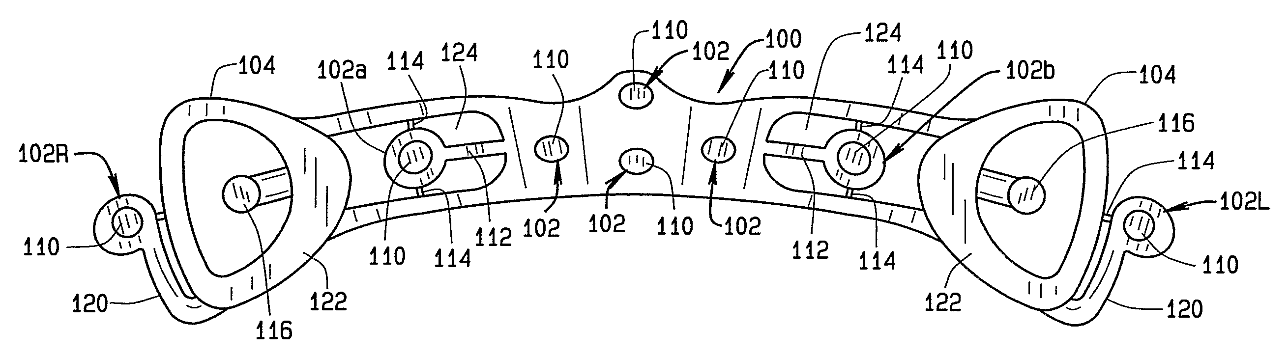
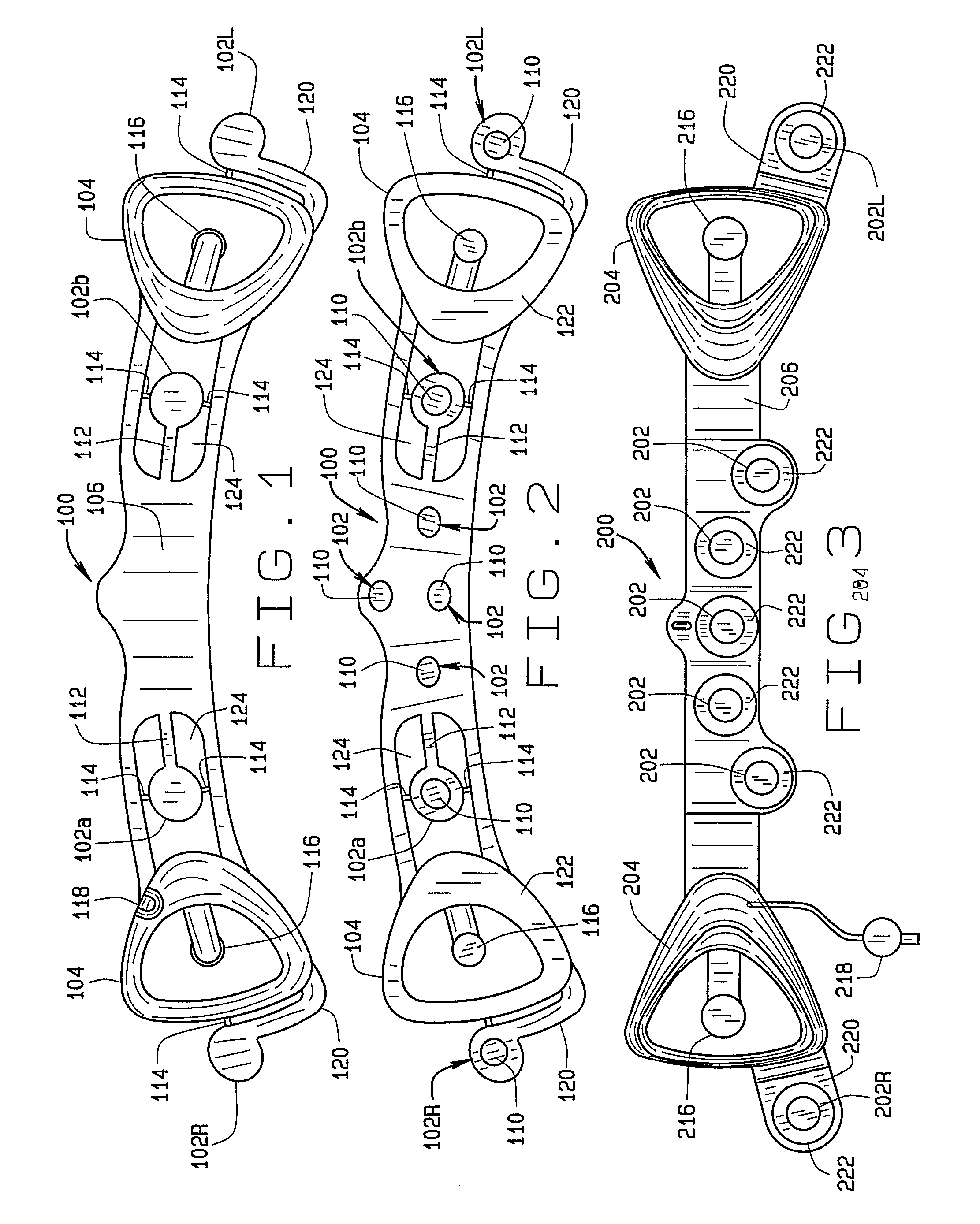
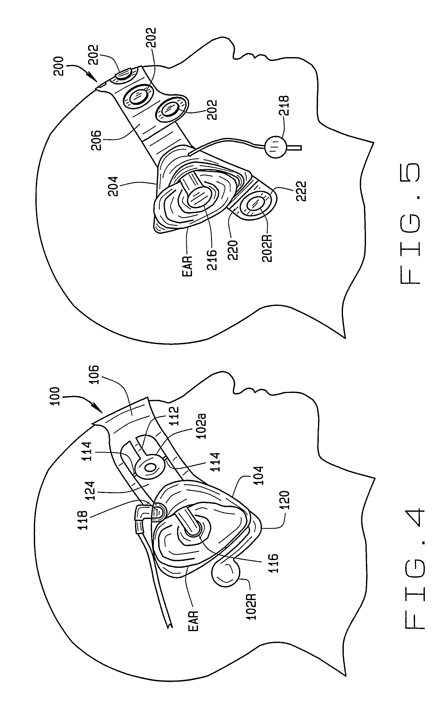
[0023]The present invention provides a disposable electrode array 100 adapted to quickly and properly apply required electrode sensors to a patient. The disposable electrode array 100 integrates a set of electrode sensors 102, such as AEP sensors and EEG sensors, into a one-piece array. The electrode sensors 102 are adjustable to permit the placement of the electrode sensors 102 to the individual patient. Preferably, the use of elastic materials in the construction of the disposable electrode array 100 enables the electrode appliance to accommodate a variety of patient head sizes and shapes. Ear loops 104 dis...


PUM


Abstract

A disposable electrode array 100, 200 including a flexible member 106, 206 in which a plurality of electrodes 102, 202 are disposed, having a shape adapted to contact the forehead skin surface on a human patient. A pair of ear loops 104, 204 coupled to the disposable electrode array 100, 200 secure the disposable electrode array 100, 200 about the patient's ears, with the flexible member 106, 206 disposed across the patient's bow, retaining the electrodes 102, 202 against the skin surface. Additional electrodes 102, 202 are disposed in proximity to the ear loops 104, 204 and are configured to contact the skin surface behind the patient's ears. An auditory stimulus delivery element 116, 216 is coupled with each of the ear loops 104, 204, and positioned to seat in proximity to the patient's ear canal for the delivery of auditory stimulus. Electrical conductors associated with the electrodes 102, 202 and the stimulus delivery elements 116, 216 are routed within the flexible member 106, 206 to a common external connection point 118, 218 for connection to an external system. The disposable electrode array 100, 200 may be configured for both evoking and measuring evoked bio-potentials in the human subject, or for measuring bio-potentials evoked using a separate stimulus delivery system.

Description

CROSS-REFERENCE TO RELATED APPLICATIONS[0001]The present application is related to, and claims priority from, U.S. Provisional Patent Application Ser. No. 60 / 719,943 filed on Sep. 23, 2005, which is herein incorporated by reference.TECHNICAL FIELD[0002]The present invention related generally to electrodes for receiving bio-potential signals from skin surfaces of a human patient, and in particular, to a disposable electrode array integrating auditory evoked potential (AEP) and electro-encephalogram (EEG) electrodes into a single appliance for adjustable placement on the head of a human patient.BACKGROUND ART[0003]When multiple nerve cells or muscle cells depolarize simultaneously or sequentially, they generate a bio-potential that can be detected as an electrical signal by an externally positioned electrical circuit. External electrical circuits have long been used to measure such relatively small but measurable bio-potentials. The electroencephalogram (EEG) and Auditory Evoked Poten...

Claims


Application Information

Patent Timeline
Patent Type & Authority Patents(United States)
IPC IPC(8): A61B5/0478A61B5/0484
CPCA61B5/0478A61B5/04845A61B5/6814A61B5/6803A61B2562/164A61B5/38A61B5/291
Inventor CAUSEVIC, ELVIRCHRISTIANSEN, CHRISTIANMETZGER, DANIEL
Owner BRAINSCOPE SPV LLC
Why Eureka
Try Eureka