Power unit and vehicle equipped with it

a power unit and power technology, applied in the field of power units, can solve the problems of spoiling the assembly and maintenance facility of the vehicle, the bottom end of the power unit may be too low to ensure sufficient ground clearance, etc., to achieve the effect of enhancing the efficiency of power transmission from the transmission output shaft to the propeller shaft, reducing noise or vibration, and reducing power loss

Active Publication Date: 2013-03-26
KANZAKI KOKYUKOKI MFG +1
View PDF23 Cites 10 Cited by
  • Summary
  • Abstract
  • Description
  • Claims
  • Application Information

AI Technical Summary

Benefits of technology

[0016]Incidentally, the above-mentioned fore-and-aft axial power unit, having the end portion of the transmission output shaft laterally offset from the belt of the belt transmission, spoils its advantage in minimization in the lateral direction of the vehicle because the arrangement of the end portion of the transmission output shaft expands the power unit in the lateral direction of the vehicle.
[0032]Preferably, in the vehicle, a base having an opening covers the belt transmission of the power unit, and a driver's seat is mounted on the base so as to cover the opening. The seat is movable so as to open the opening of the base for enabling access to the belt transmission via the opening. Therefore, a space below the driver's seat is utilized for arranging the belt transmission so as to reduce a dead space, thereby minimizing the vehicle. Further, due to the easy access to the belt transmission, the belt transmission is improved in maintenanceability. Additionally, the base of the driver's seat serves as a cover for covering the opening for access to the belt transmission, thereby reducing costs.

Problems solved by technology

If the top end of the portion of the belt transmission is lowered, a bottom end of the power unit may be too low to ensure sufficient ground clearance of the vehicle.
However, reduction of the gap between the transmission input shaft and the transmission output shaft causes a complication of the mechanism of the second transmission because it requires an increase of the number of gears for ensuring a required gear ratio between the transmission input shaft and the transmission output shaft, for example, thereby spoiling its facility of assembling and maintenance.

Method used


Image

  • Power unit and vehicle equipped with it
  • Power unit and vehicle equipped with it
  • Power unit and vehicle equipped with it

Examples


Embodiment Construction

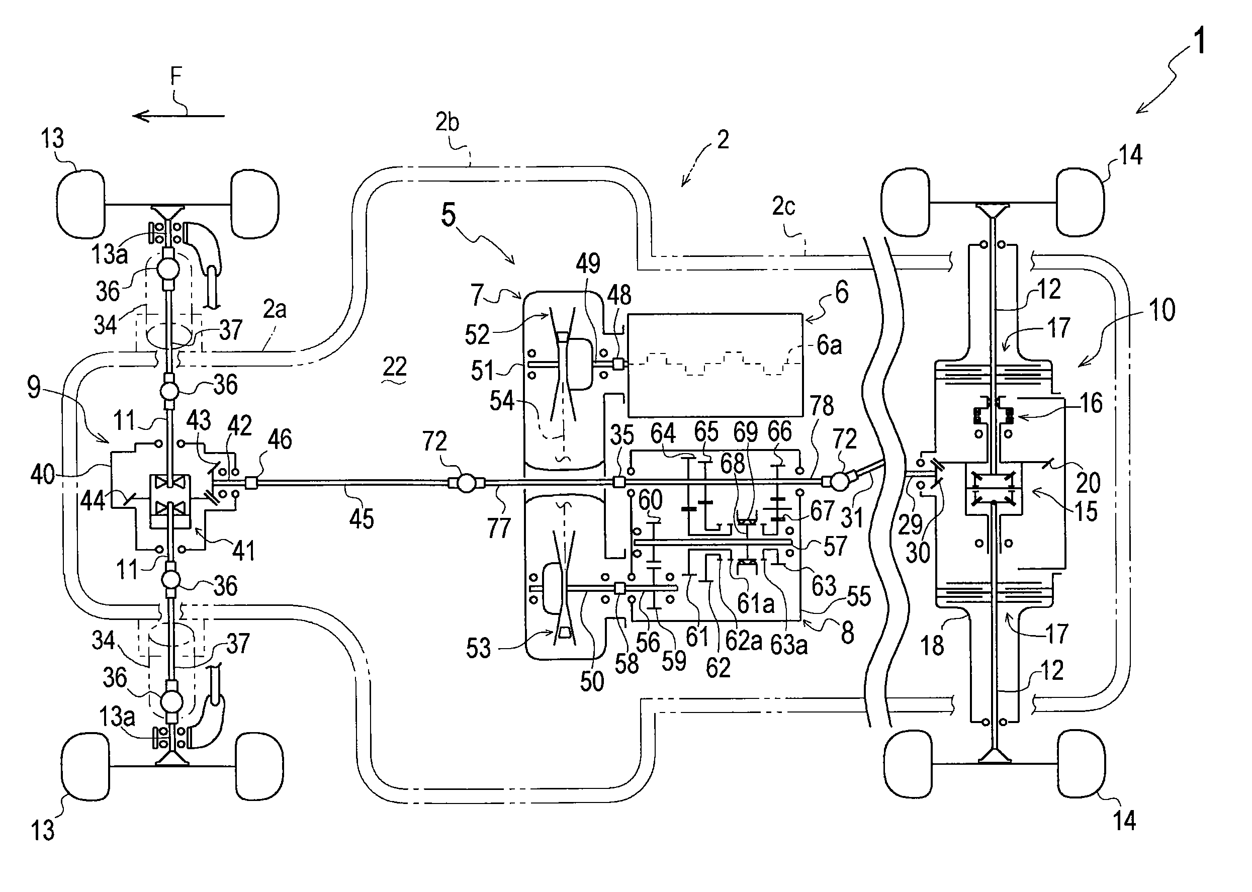
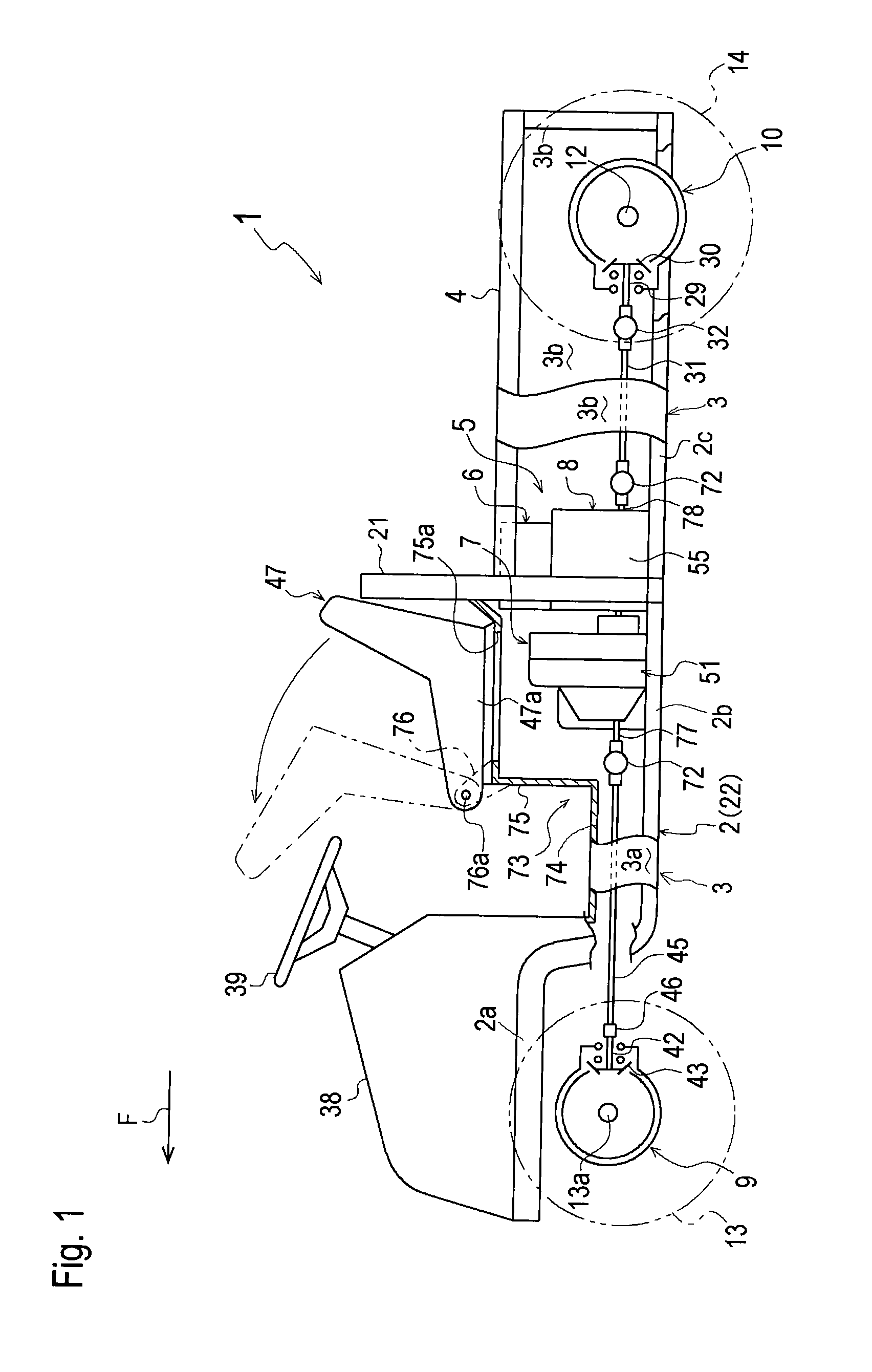
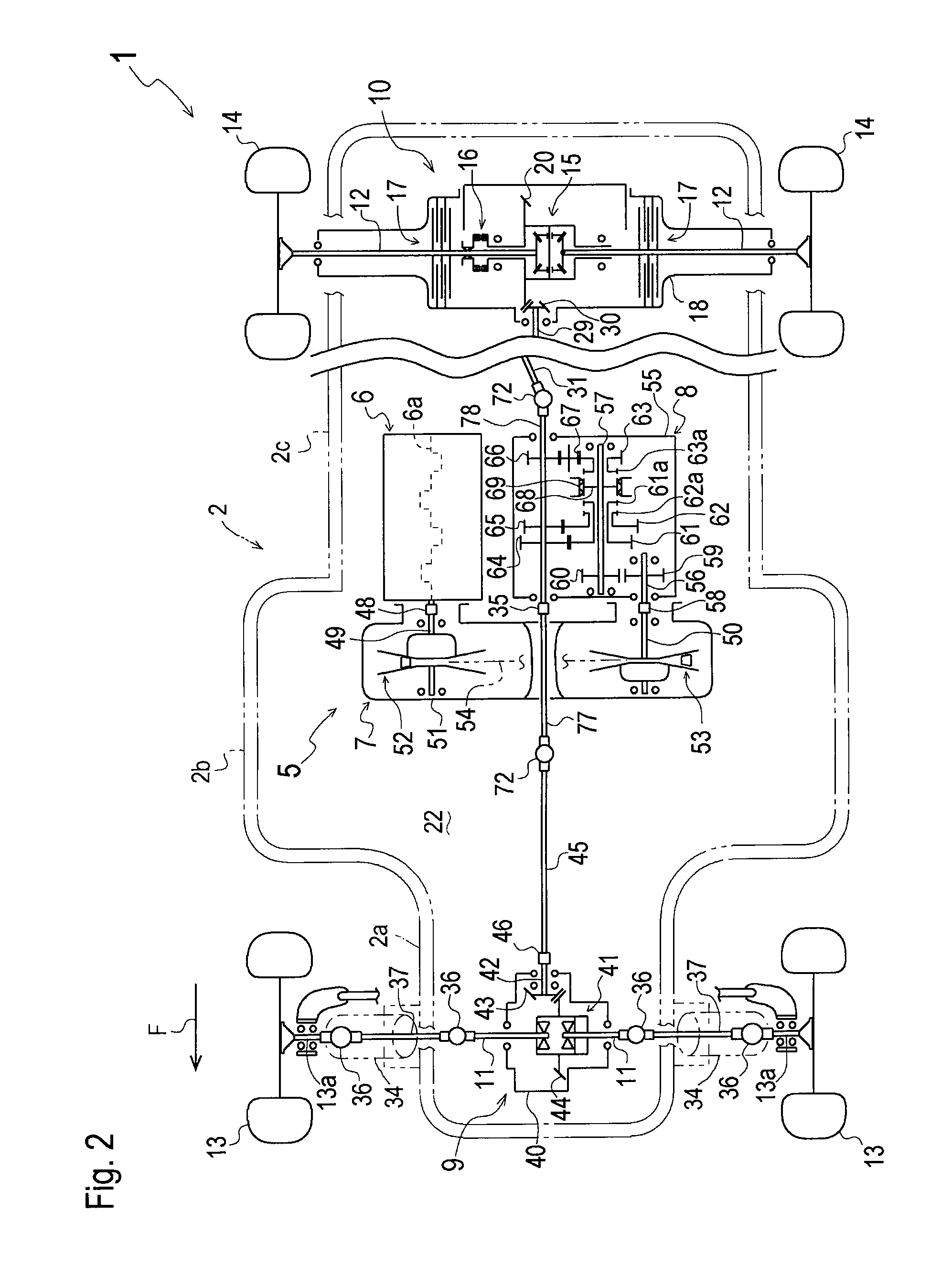
[0045]Embodiments of the inventions will be described. Hereinafter, positions and directions of respective elements and portions will be referred to on an assumption that an arrow F in each of drawings designates a forward traveling direction of a four-wheel drive utility vehicle serving as a multi-wheel drive vehicle.

[0046]Referring to FIGS. 1 and 2, a general structure of a four-wheel drive utility vehicle 1 (hereinafter, simply referred to as vehicle 1) will be described. A frame 2 and fenders 3 (including fenders 3a and 3b) provided upright on right, left and rear ends of frame 2 constitute a vehicle body of vehicle 1. A bottom plate (not shown) is spread over a bottom end of entire frame 2 and is surrounded by fenders 3 so as to support a power unit 5 mounted on a top surface thereof at a substantially fore-and-aft middle portion of vehicle 1.

[0047]Frame 2 includes a front frame portion 2a, a middle frame portion 2b and a rear frame portion 2c, which are joined to one another s...


PUM


Abstract

A power unit includes an engine, a belt transmission driven by the engine, and a second transmission driven by the belt transmission. The engine includes an engine output shaft having an end portion projecting outward from the engine. The second transmission includes a transmission input shaft and a transmission output shaft having respective end portions projecting outward from the second transmission. The belt transmission includes a drive pulley provided on the end portion of the engine output shaft, a driven pulley provided on the end portion of the transmission input shaft, and a belt looped over the drive and driven pulleys. The belt has first and second portions between the drive and driven pulleys. The first portion runs from the drive pulley to the driven pulley. The second portion runs from the driven pulley to the drive pulley. The end portion of the transmission output shaft is extended through a portion of the belt transmission between the drive and driven pulleys and between the first and second portions of the belt so as to project outward from the belt transmission.

Description

BACKGROUND OF THE INVENTION[0001]1. Field of the Invention[0002]The present invention relates to a power unit including an engine, a belt transmission driven by the engine, and a second transmission, such as a gear transmission, driven by the belt transmission, and relates to a vehicle, especially, a multi-wheel drive vehicle such as a four-wheel drive vehicle, equipped with the power unit.[0003]2. Related Art[0004]As disclosed in JP 2006-76548 A, a four-wheel drive utility vehicle, serving as a conventional typical multi-wheel drive vehicle, is equipped with a power unit for driving both a front wheel axle and a rear wheel axle. The power unit includes an engine, a belt transmission driven by the engine, and a second transmission, such as a gear transmission, driven by the belt transmission. The second transmission includes a first output portion for driving one of the front and rear wheel axles, and a second output portion for driving the other of the front and rear wheel axles.[0...

Claims


Application Information

Patent Timeline
Patent Type & Authority Patents(United States)
IPC IPC(8): B60K17/34
CPCB60K17/08B60K17/34B60K17/342B60Y2200/86
Inventor KOCHIDOMARI, YOSHITAKANISHIMOTO, SHUJISWANSON, LARRYKOVALASKE, JAMIEWADE, JEREMIEBIERSDORF, NICHOLAS
Owner KANZAKI KOKYUKOKI MFG
Why Eureka
Try Eureka