
Substrate Transfer Apparatus, Component Mounting Equipment, and Substrate Transfer Method

a technology of substrate transfer apparatus and component mounting equipment, which is applied in the direction of non-linear optics, instruments, manufacturing tools, etc., can solve the problems of difficult to efficiently move the above-mentioned large-sized substrate, inability to achieve efficient delivery of substrate between the substrate stage and the substrate transfer apparatus at the substrate taking-over position, and the dimension in the depth direction intersecting the substrate transfer direction of the component mounting equipment can be reduced, and the transferring time of the substrate within the component mounting equipment can be shortened

Inactive Publication Date: 2008-08-14
PANASONIC CORP
View PDF3 Cites 8 Cited by
  • Summary
  • Abstract
  • Description
  • Claims
  • Application Information

AI Technical Summary

Benefits of technology

[0032]According to the present invention, the delivery of the substrate at the substrate taking-over position can be executed efficiently and rapidly because the first and second holding sections releasably holding the lower surface of the substrate is opposed to each other with the interval in the direction intersecting the transfer direction of the substrate. Further, the dimension in the depth direction intersecting the substrate transfer direction of the component mounting equipment can be reduced. As a result, the transferring time of the substrate within the component mounting equipment can be shortened and maintenanceability can also be improved. Especially, even in the case of a large substrate, the delivery of the substrate can be executed efficiently and the dimension in the depth direction of the component mounting equipment can be minimized.
[0033]Further, when the second substrate stage is at the second substrate taking-over position and the second substrate stage is at the second height position at which it abuts against the lower surface of the substrate held by the first and second substrate holding sections of the substrate transfer apparatus, in cases where the detection value of the holding force detected by the sensor is less than a threshold, that is, in cases where the holding force of the holding mechanism is insufficient, the substrate is pushed against the second substrate stage by the warpage correction section. Therefore, the substrate can be delivered from the first and second substrate holding sections of the substrate transfer apparatus to the second substrate stage in a state of high flatness in which the warpage has been corrected. Further, the positional displacement of the substrate during delivery due to warpage of the substrate can be prevented. As a result, the accuracy of the mounting operation for the substrate with respect to the working section can be improved. Furthermore, because the holding force with which the holding mechanism holds the substrate on the substrate stage rises rapidly due to the correction of the warpage of the substrate, the time necessary for delivering the substrate can be shortened and the takt can be improved.

Problems solved by technology

Recently, the substrates to which mounting operations are carried out by such component mounting equipments have tended to increase in size.
Due to that movements in these two directions are required, efficient delivery of the substrate between the substrate stage and the substrate transfer apparatus at the substrate taking-over position can not be achieved.
Particularly, it is difficult to efficiently move the above-mentioned large size substrate in these two directions.
The increased dimension in the depth direction increases time necessary for transferring the substrate within the component mounting equipment and also decreases maintenanceability of the component mounting equipment.
Furthermore, large warpage can be readily generated for the large size substrate comparing with a small substrate.
The positional shift of the substrate during the delivery can lower operational accuracy at the working section.
For example, the positional shift of the substrate during delivery can lower accuracy of mounting position when the pre-press bonding is executed.
Further, the warped substrate causes air leakage which extends time necessary for the suction force to rise to an efficient value, resulting in tact loss.

Method used


Image

  • Substrate Transfer Apparatus, Component Mounting Equipment, and Substrate Transfer Method
  • Substrate Transfer Apparatus, Component Mounting Equipment, and Substrate Transfer Method
  • Substrate Transfer Apparatus, Component Mounting Equipment, and Substrate Transfer Method

Examples


Embodiment Construction

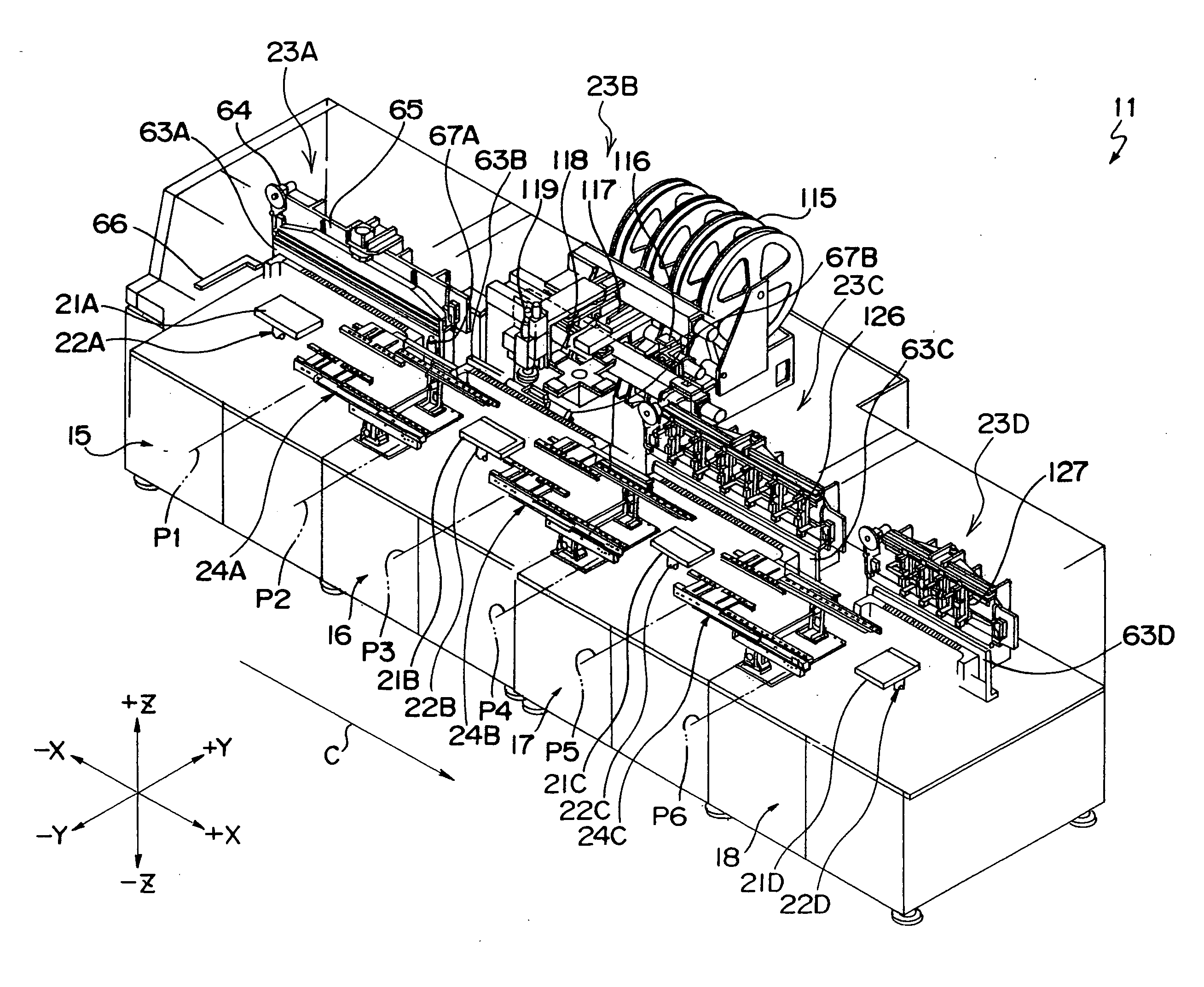
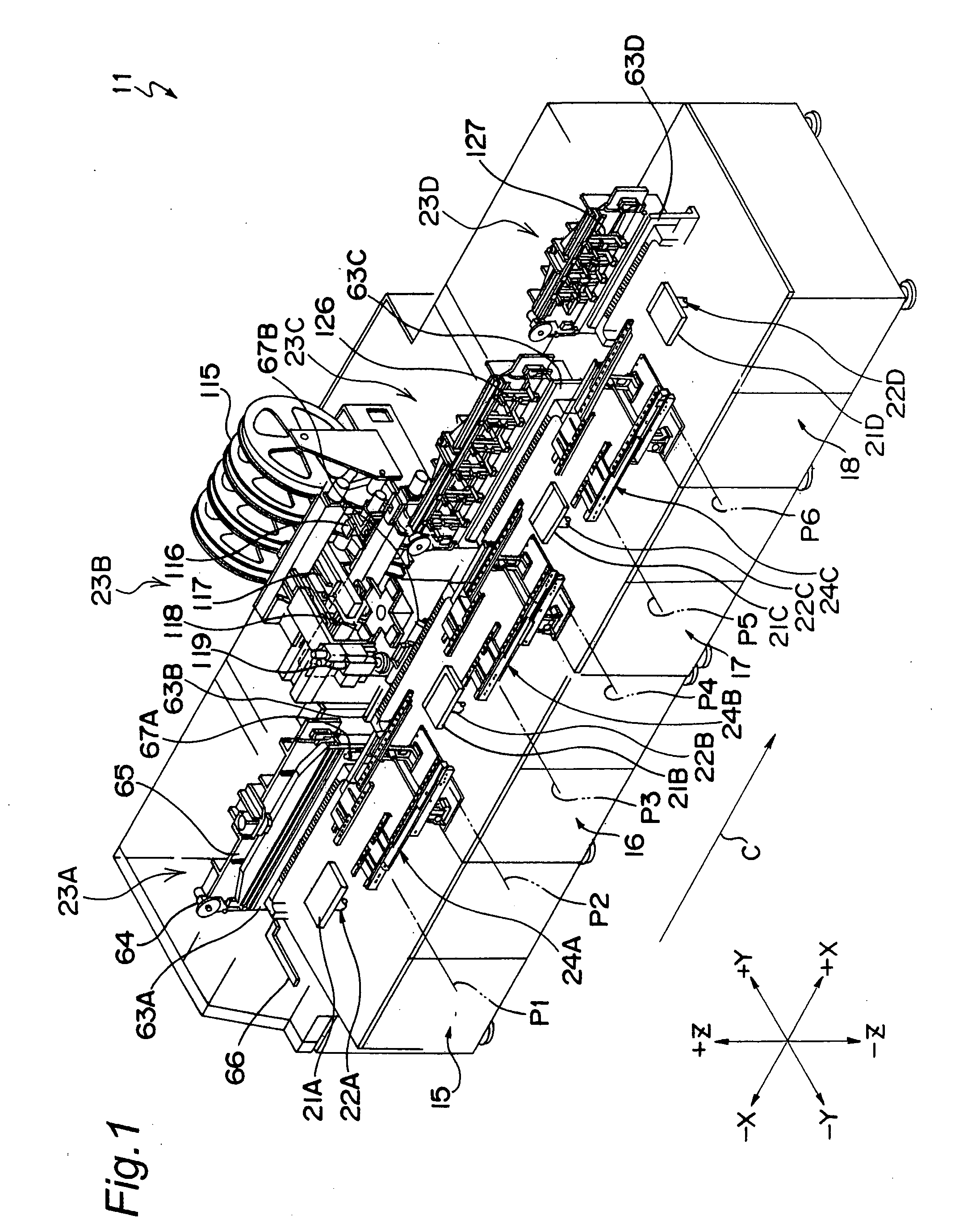
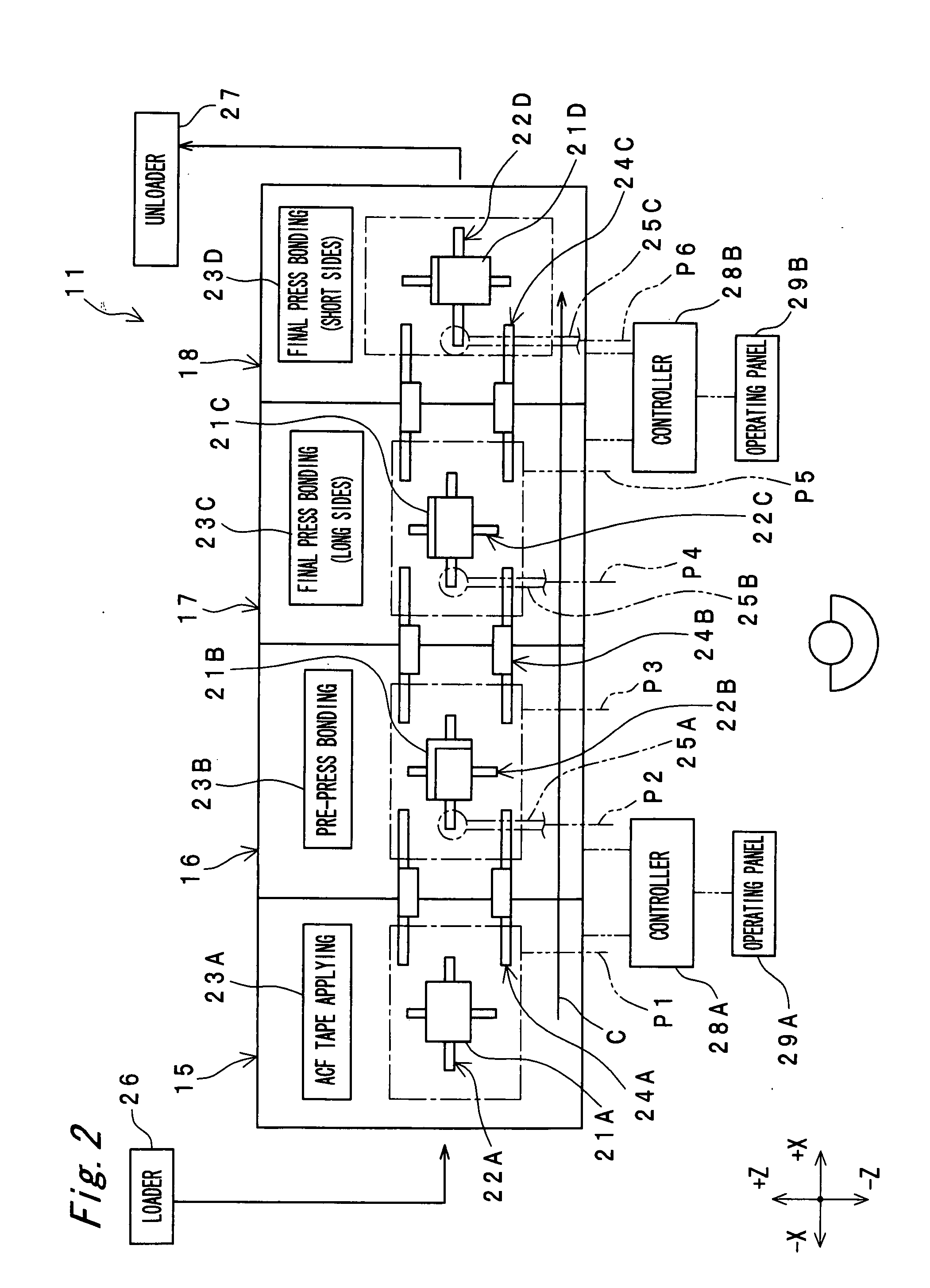
[0161]FIGS. 1 and 2 show a component mounting equipment 11 according to an embodiment of the present invention. The component mounting equipment 11 is an apparatus for mounting a component 13 onto a substrate 12 shown in FIG. 3.

[0162]The substrate 12 will now be described with reference to FIG. 3. In this embodiment, substrate 12 is a liquid-crystal display substrate (LCD substrate). However, substrate 12 may be a glass substrate such as a plasma display substrate (PDP substrate) or may be a substrate other than a glass substrate. The substrate 12 has an oblong shape in plain view. A long and narrow region extending along one of a pair of opposite long sides of the substrate 12 is a first mounting region 12a in which the component 13 is mounted. Further, the long and narrow region extending along one of a pair of opposite short sides is a second mounting region 12b in which the component 13 is mounted. A portion close to the first mounting region 12a of the substrate 12 is referred ...


PUM

PropertyMeasurementUnit
sizeaaaaaaaaaa
sizeaaaaaaaaaa
sizeaaaaaaaaaa

Abstract

A substrate transfer apparatus 24A of a component mounting equipment has linear motion guides 78A and 78B and substrate holding sliders 79A and 79B. The linear motion guides 78A and 78B extend in a transfer direction “C” from a first substrate taking-over position P1 to a second substrate taking-over position P2 and are opposed to each other with an interval G1 in a direction orthogonal to the transfer direction “C”. The substrate holding sliders 79A and 79B can move along the linear motion guides 78A and 78B, are opposed to each other with an interval G2 in the direction orthogonal to the transfer direction C, and releasably hold a lower surface of the substrate 12. The substrate holding sliders 79A and 79B move reciprocatingly in the transfer direction of the substrate 12 between the first and second substrate taking-over positions by an X-axis drive mechanism 87.

Description

TECHNICAL FIELD[0001]The present invention relates to a substrate transfer apparatus, method for transferring substrates including glass substrates such as a liquid-crystal display substrate (LCD substrate) or a plasma display substrate (PDP substrate), and a component mounting equipment for mounting components including electronic components such as IC chips or various semiconductor devices onto these types of substrate.BACKGROUND ART[0002]An example of conventional component mounting equipment is disclosed in Patent Publication 1. Referring to FIG. 20, a reference numeral “1” denotes a substrate stage for holding a substrate 2. Suction holes (not illustrated) are formed in the substrate stage 1 which is a rigid body and a lower side of the substrate 2 is held by suction force acting through the suction holes. Further, a reference numeral “3” denotes a substrate transfer apparatus that transfers the substrate 2 and delivers the substrate 2 to and from the substrate stage 1. The sub...

Claims


Application Information

Patent Timeline
Patent Type & Authority Applications(United States)
IPC IPC(8): H01L21/677
CPCG02F1/1333G02F2001/133354H05K13/0061Y10T29/53178Y10T29/53191Y10T29/4913Y10T29/49133G02F1/133354H01L21/67144H01L21/67236H01L21/67721H01L21/6838
Inventor TSUJI, SHINJIROMURATA, TAKAHIKOFUJIWARA, KEIJIODAWARA, KOZO
Owner PANASONIC CORP
Learn More