Vehicle With Electric Transaxle

a transaxle and electric technology, applied in the field of vehicles, can solve the problems of cvt being delayed in the reduction of output speed, and unable to serve as the engine brake in at least a part of the overall speed shift range, so as to simplify and economize the structure, and achieve the effect of reducing the power consumption of the vehicle, reducing the cost of operation and high torqu

Active Publication Date: 2015-07-16
KANZAKI KOKYUKOKI MFG
View PDF20 Cites 11 Cited by
  • Summary
  • Abstract
  • Description
  • Claims
  • Application Information

AI Technical Summary

Benefits of technology

[0012]Therefore, the vehicle can travel silently by the electric power of the electric motor. The vehicle is advantageous in expanding an available space, such as an operator's space involving the seat forward (or rearward) of the load carrying bed, while ensuring compactness of the entire vehicle because a dead space below the load carrying bed is utilized for arranging the transaxle including the electric motor and because the dead space below the load carrying bed or a dead space below the seat is utilized for arranging the battery. Further, the battery can be exchanged for a new battery easily by moving the load carrying bed or the seat for opening the space below the load carrying bed or the seat, thereby improving maintenanceability of the battery.
[0040]Therefore, a vehicle equipped with an engine and the transmission assembly can save the engine power consumption with the assistance of the motor generator functioning as the electric motor, and can efficiently reduce its traveling speed by the regeneration brake function of the motor generator functioning as the generator in such a case where the vehicle descends a slope. The transmission assembly can be easily and compactly provided with the motor generator by extending the one of the plurality of shafts of the second transmission on the side of the housing opposite to the belt transmission so as to avoid interference with the belt transmission.

Problems solved by technology

The defect of the CVT is a delay of reduction of output speed.
Such an efficient reduction of traveling speed is called “engine brake”, however, the CVT cannot serve as the engine brake in at least a part of its overall speed shift range.

Method used


Image

  • Vehicle With Electric Transaxle
  • Vehicle With Electric Transaxle
  • Vehicle With Electric Transaxle

Examples


Embodiment Construction

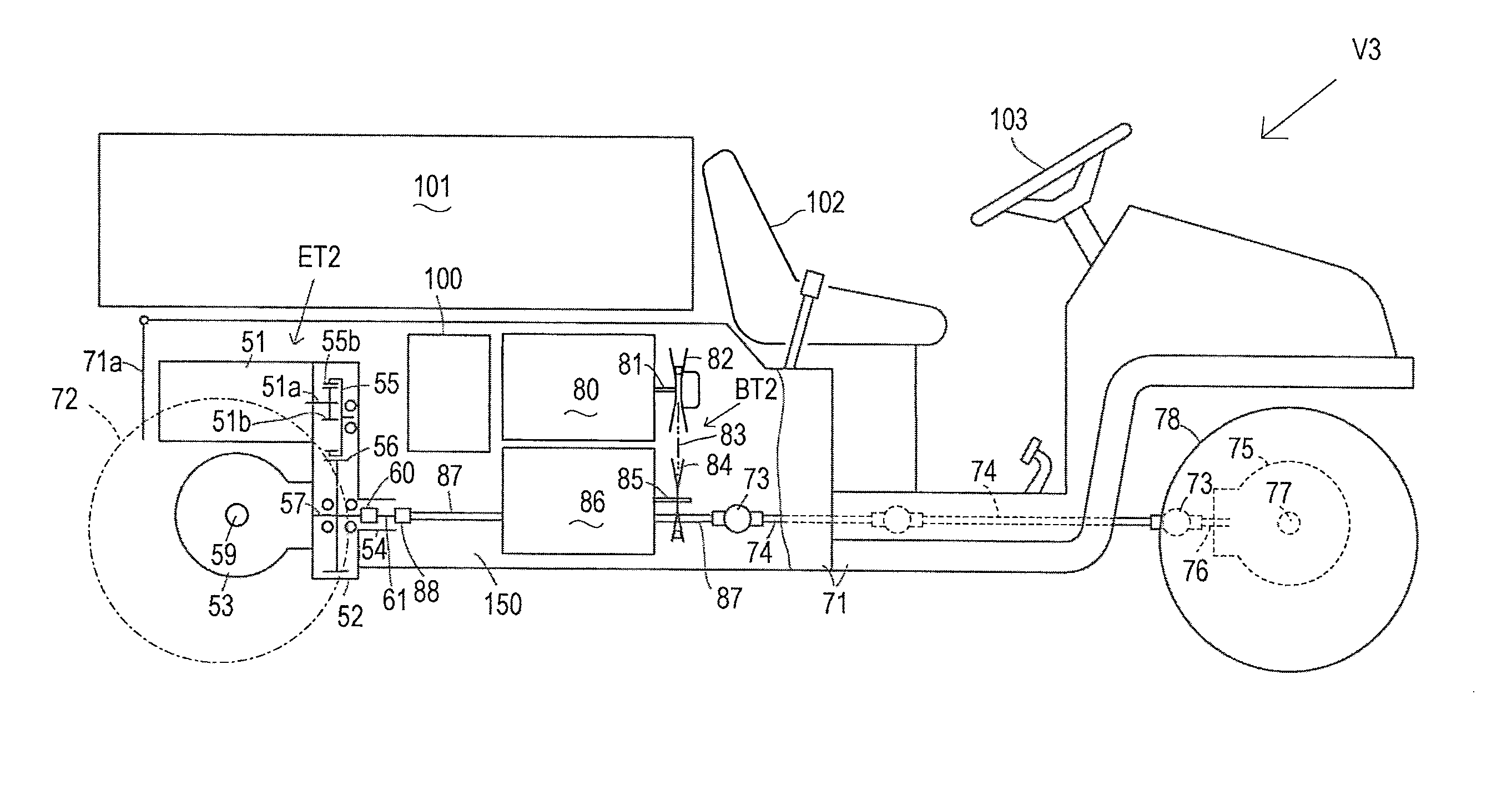
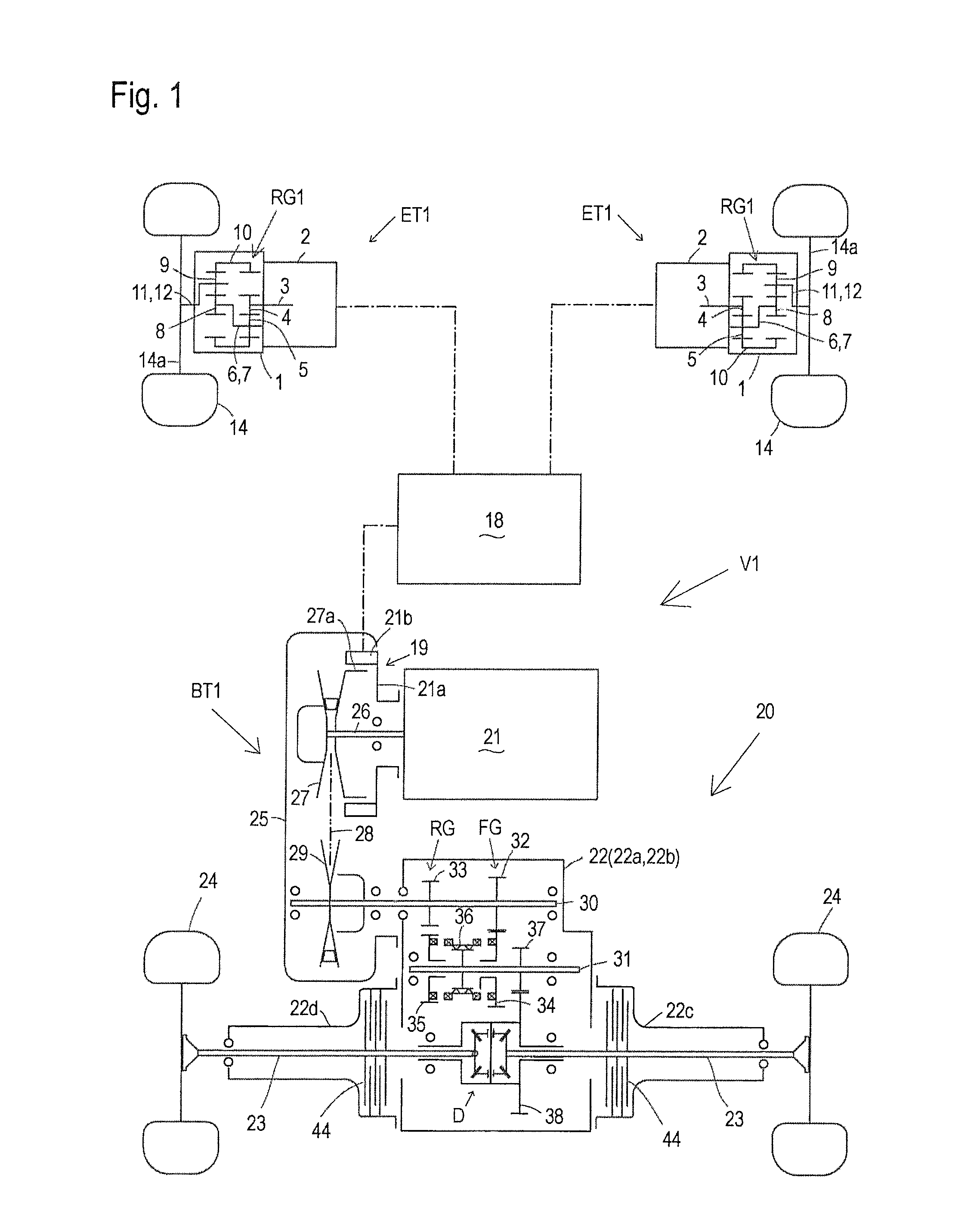
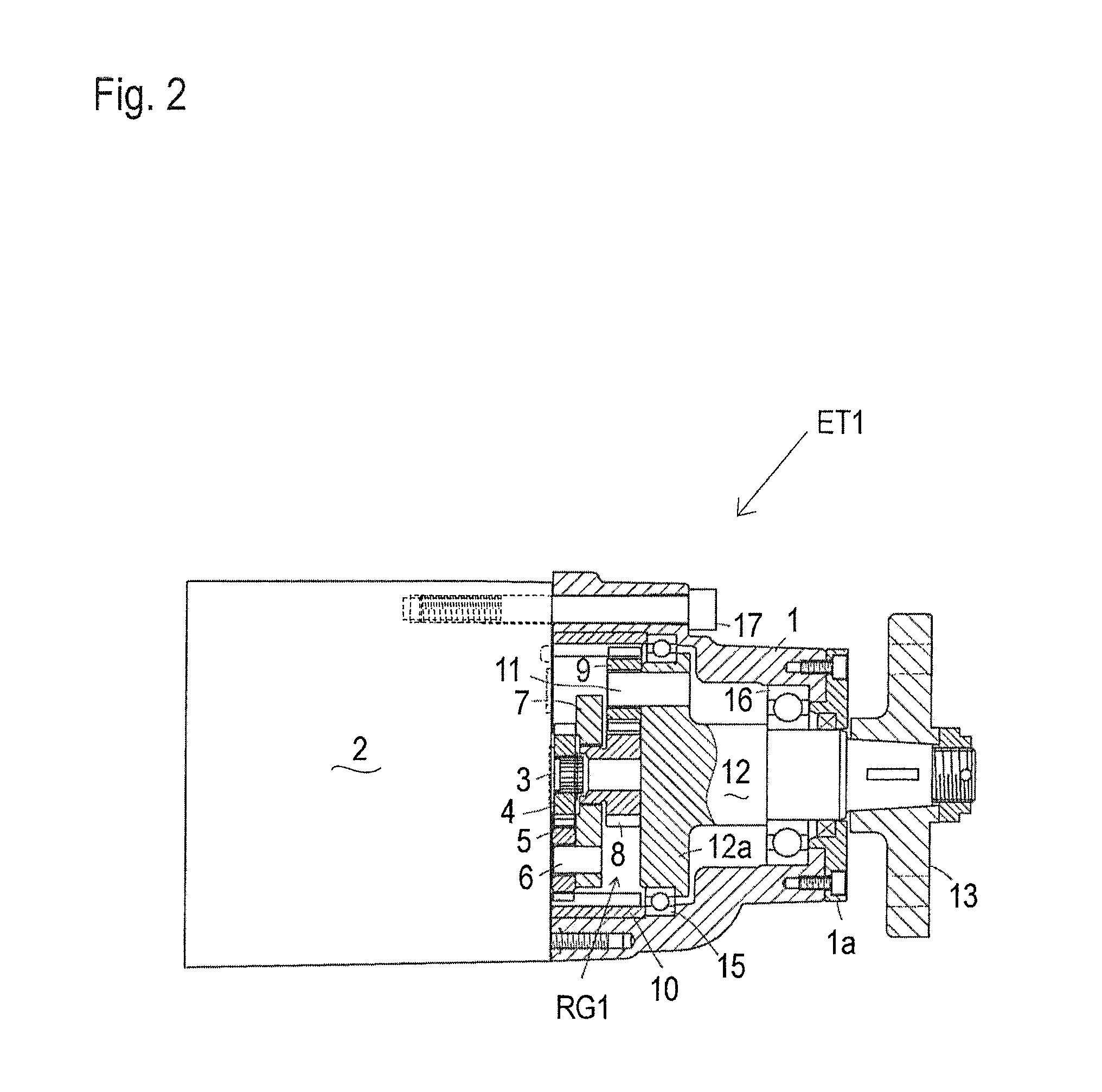
[0062]Referring to FIGS. 1, 2 and 3, a hybrid vehicle (hereinafter, simply referred to as “vehicle”) V1 will be described. Vehicle V1 is a utility vehicle, for example. Vehicle V1 is equipped with a pair of electric transaxles ET1 serving as right and left front transaxles for driving respective right and left front wheels 14, and is equipped with an engine-transmission assembly 20 for driving right and left rear wheels 24. Engine-transmission assembly 20 is a combination of an engine 21 and a transmission assembly, and the transmission assembly includes a transaxle casing 22, and a belt transmission BT1 for transmitting power from engine 21 into transaxle casing 22. Right and left rear wheels 24 are provided on distal ends of respective right and left rear axles 23 supported by transaxle casing 22. Transaxle casing 22 incorporates a forward traveling gear train FG, a backward traveling gear train RG, and a differential gear unit D differentially connecting proximal ends of right an...


PUM


Abstract

A vehicle comprises a transaxle, a battery and a load carrying bed. The transaxle includes a casing incorporating a drive train and supporting an axle and includes an electric motor mounted on the casing to drive the axle via the drive train. The battery is provided for supplying electric power to the electric motor. The transaxle and the battery are disposed below the load carrying bed so as to overlap the load carrying bed when viewed in plan.

Description

CROSS-REFERENCE TO RELATED APPLICATION[0001]This application is a continuation of U.S. application Ser. No. 13 / 623,663, filed Sep. 20, 2012, which claims the benefit of U.S. Application No. 61 / 538,641, filed on Sep. 23, 2011, which benefit is also claimed by this application. These applications are hereby incorporated by reference in their entirety.BACKGROUND OF THE INVENTION[0002]1. Field of the Invention[0003]The present invention relates to a vehicle, such as a utility vehicle, equipped with an electric transaxle integrated with an axle and an electric motor for driving the axle. Also, the present invention relates to a transmission assembly adapted to be driven by an engine and provided with an electric motor for assisting the engine. Especially, the transmission assembly includes a continuously variable belt transmission (CVT).[0004]2. Background Art[0005]As disclosed by U.S. Pat. No. 7,926,387 B, a conventional utility vehicle is equipped with a rear transaxle under a load car...

Claims


Application Information

Patent Timeline
Patent Type & Authority Applications(United States)
IPC IPC(8): B60K6/40B60K17/356B60K6/48B60K17/04B60K6/52B60K7/00
CPCB60K6/40B60K6/52B60K7/0007Y10S903/951B60K17/043B60K17/356B60K2007/0038B60K6/48B60K17/344F16H37/021F16H37/065B60K17/046B60K17/22B60K2007/0092B60K6/485B60K6/543Y02T10/62
Inventor KOCHIDOMARI, YOSHITAKANISHIZAWA, TAKASHI
Owner KANZAKI KOKYUKOKI MFG
Why Eureka
Try Eureka