Method for casting air sucking valve steel casting part

A technology for steel castings and exhaust valves, which is applied in the direction of casting molding equipment, casting molds, and casting mold components. Small thermal crack phenomenon, excellent surface quality, and the effect of improving yield

Active Publication Date: 2013-04-24
CRRC QISHUYAN INSTITUTE CO LTD +1
View PDF3 Cites 22 Cited by
  • Summary
  • Abstract
  • Description
  • Claims
  • Application Information

AI Technical Summary

Problems solved by technology

At present, when casting thin-walled closed structures such as valve casings, the exterior and sand cores are made of water glass quartz sand. Although the quartz sand can obtain excellent surface quality, due to the poor yield of the water glass quartz sand, it is used in When the molten steel solidifies and shrinks, the shell wall, especially the inner cavity wall, is prone to thermal cracks due to uneven thickness, resulting in a low pass rate of castings
Furthermore, the two side flanges, the end flanges, the valve stem hole and the inner flange used for connection on the valve housing are all precision-machined parts, which need to bear a certain load during use, so this part needs to have a good The compactness, but using conventional casting methods, defects such as shrinkage porosity, pores and sand inclusions will appear on these processed surfaces, so that the qualified rate of castings is not high, and the production cost is increased.

Method used


Image

  • Method for casting air sucking valve steel casting part
  • Method for casting air sucking valve steel casting part

Examples


Embodiment Construction

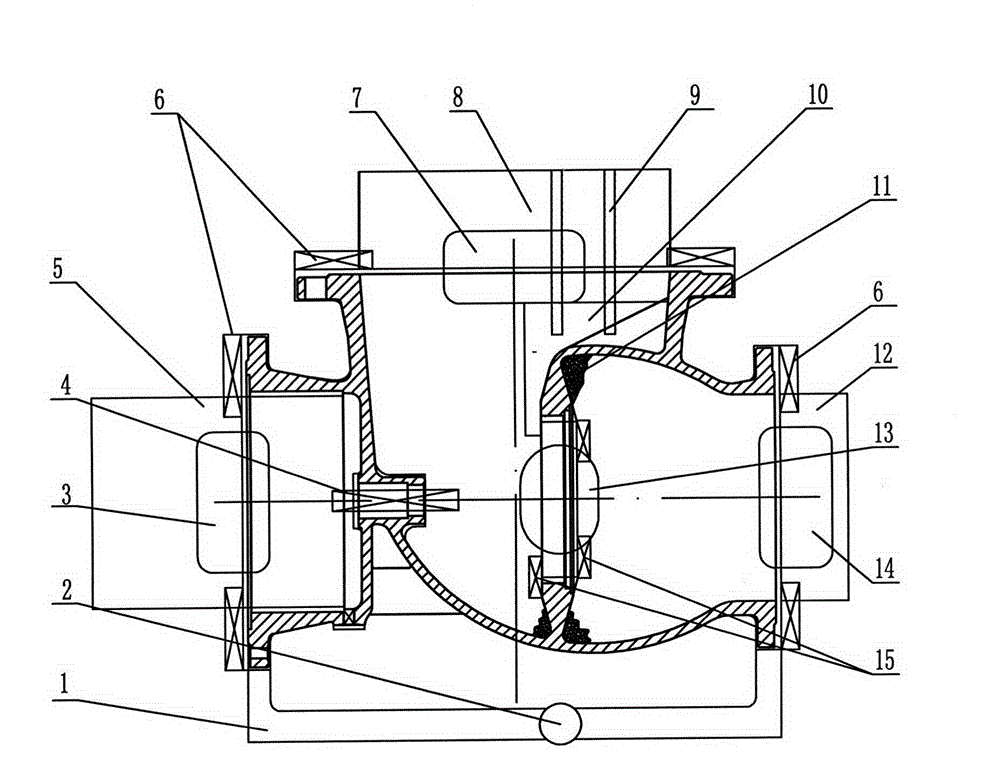
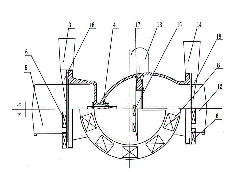
[0016] See figure 1 , 2 As shown, the casting method of the air extraction valve valve casing steel casting of the present invention includes making metal molds, moulding, core making, box closing, charge smelting, pouring, cooling and casting cleaning.

[0017] (1) Use the central section of the flange hole on the first side and the flange hole on the second side of the casting as the upper and lower parting surfaces to make a metal mold, make the upper and lower molds with water glass quartz sand, and release the mold after hardening with carbon dioxide gas , and brush zircon powder paint on the upper and lower surface. Use water glass limestone sand as the back sand of the sand core, and water glass quartz sand as the face sand of the sand core to make sand cores. The back sand is filled in the face sand, and the thickness of the face sand is controlled at 20-50mm. For example, the thickness of the face sand is controlled at 22mm. , 25mm, 30mm, 35mm, 40mm or 45mm, etc., c...


PUM

PropertyMeasurementUnit
thicknessaaaaaaaaaa

Abstract

The invention relates to a method for casting an air sucking valve steel casting part. The method comprises the steps (1) using central cross sections of flange holes on two sides of the casting part as parting surfaces, manufacturing a metal mold, using water glass quartz sand to manufacture an upper portion and a lower portion, using water glass limestone sand as back sand, using the water glass quartz sand as facing sand to manufacture sand cores and brushing zircon power coatings on the surfaces of the upper portion, the lower portion and the sand cores; (2) placing the sand cores into a cavity of the lower portion, placing outer cold irons on flange end faces of the lower portion, placing open risers and riser pads on the upper portion, placing second outer cold irons on two end faces of an inner flange of the lower portion, correspondingly placing blind risers and riser pads on the upper portion, placing inner cold irons at the valve rod hole positions of a second sand core and a fourth sand core and leading a straight pouring channel and a horizontal pouring channel of a pouring system into flange edges on two sides at the parting surface positions; (3) assembling the mold after the cores fall; (4) smelting furnace burden and pouring the casting part; and (5) performing cooling, mold opening and core falling to clean the casting part. By means of the method for casting the air sucking valve steel casting part, casting part cracks can be decreased, an internal structural of the casting part is compact, and the rate of finished products is high.

Description

technical field [0001] The invention relates to a casting method of a valve shell casting of an air extraction valve, which belongs to the technical field of casting. Background technique [0002] The air extraction valve housing is a commonly used air extraction device in thermal power stations. The main working environment is high temperature, high humidity and high pressure, and the harsh working environment determines the high quality requirements of the castings. Therefore, there are no requirements for the air extraction valve housing castings. Cracks, the internal structure of the casting is dense, the chemical composition and mechanical properties are qualified. At present, the valve casings of the exhaust valves are all made of ZG20CrMo material. [0003] The valve casing of the exhaust valve is a thin-walled closed shell structure with side flanges on both sides and end flanges on the upper part. Inside the shell, there is an inner cavity wall for isolating the ai...

Claims


Application Information

Patent Timeline
Patent Type & Authority Applications(China)
IPC IPC(8): B22D15/02B22C1/00B22C3/00
Inventor 肖恭林李伟桑子雷贾旭曹松詹璐瑶徐建国
Owner CRRC QISHUYAN INSTITUTE CO LTD
Why Eureka
Try Eureka