Self-positioning vacuum brazing technique for multi-cavity electrical bridge waveguide

A brazing process and self-positioning technology, which is applied in the direction of manufacturing tools, welding equipment, metal processing equipment, etc., can solve the difficulty of ensuring the dimensional accuracy of the multi-cavity bridge waveguide, uneven heating of the multi-cavity bridge waveguide, and cavity welding deformation Large quantity and other problems, to achieve the effect of improving dimensional accuracy and surface roughness, reducing production and processing procedures, and high assembly accuracy

Inactive Publication Date: 2013-12-11
CHENGDU JINJIANG ELECTRONICS SYST ENG
View PDF5 Cites 19 Cited by
  • Summary
  • Abstract
  • Description
  • Claims
  • Application Information

AI Technical Summary

Problems solved by technology

Such a production method has the following disadvantages: ①Multiple times of flame brazing require multiple pre-welding surface treatment and post-welding flux cleaning processes, the processing technology is complicated, and the production cycle is long; ②When welding flanges at both ends of the forming cavity , the two need to be precisely positioned and assembled, and the operator has a large workload and high skill requirements; ③ In order to make the brazing filler metal wet, capillary flow, and fill the gap in the base metal gap, flux is usually used during welding , due to the use of highly corrosive fluorine-containing flux for multiple flame brazing, it is difficult to completely remove the residual flux in the cavity, and the waveguide will be corroded to varying degrees in the future use process, and the service life will be greatly shortened; ④Multiple times of flame brazing lead to uneven local heating of the multi-cavity bridge waveguide, large cavity welding deformation, and difficult to guarantee the dimensional accuracy of the multi-cavity bridge waveguide

Method used


Image

  • Self-positioning vacuum brazing technique for multi-cavity electrical bridge waveguide
  • Self-positioning vacuum brazing technique for multi-cavity electrical bridge waveguide

Examples


Embodiment Construction

[0034] The technical solution of the present invention will be further described in detail below in conjunction with the accompanying drawings, but the protection scope of the present invention is not limited to the following description.

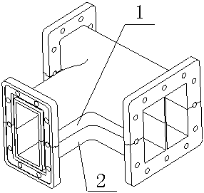
[0035] like figure 1 Shown is the multi-cavity bridge waveguide manufactured according to the process of the present invention, the self-positioning multi-cavity bridge waveguide vacuum brazing process, which includes the following steps:

[0036] (1) Raw materials are prepared, and the machining of the upper part 1 of the waveguide and the lower part 2 of the waveguide is completed according to the design.

[0037] (2) Pickling the processed waveguide upper part 1 and waveguide lower part 2 respectively; the pickling includes the following steps: Step 1: Use 60℃~80℃, 8%~10% NaOH aqueous solution to treat the waveguide upper part 1 Etch with the lower part 2 of the waveguide, and the etching time is 1 to 2 minutes; the second step: put the...


PUM


Abstract

The invention relates to a self-positioning vacuum brazing technique for a multi-cavity electrical bridge waveguide. The self-positioning vacuum brazing technique comprises the following steps of preparing materials and finishing the machining of an upper part and a lower part of the waveguide; respectively carrying out surface treatment on the machined upper and lower parts of the waveguide; producing brazing filler metals according to overall dimensions of the upper part and the lower part of the waveguide and assembling the upper part and the lower part of the waveguide and the brazing filler metals; matching the assembled electrical bridge waveguide with a work fixture and placing the assembled electrical bridge waveguide and the work fixture into a vacuum aluminum brazing furnace; carrying out vacuum brazing on the multi-cavity electrical bridge waveguide according to a vacuum brazing temperature process curve; carrying out numerical control machining on the shape of the waveguide and a ring flange; drilling and carrying out electrochemical treatment. According to the self-positioning vacuum brazing technique disclosed by the invention, the ring flange and a waveguide tube are integrally formed at one time, so that the processing work procedures are simplified, and the production period is short; a groove and a shoulder are arranged, so that self positioning is realized, combined times are reduced, and the assembly precision is high; one-time welding forming is realized by adopting vacuum brazing, and thus the deformation of cavities caused by multiple times of welding is avoided; in addition, no brazing flux is needed, and thus the corrosion of the brazing flux to the cavities is avoided, and the service life of the multi-cavity electrical bridge waveguide is prolonged.

Description

technical field [0001] The invention relates to a self-positioning multi-cavity bridge waveguide vacuum brazing process. Background technique [0002] The waveguide is used to transmit ultra-high frequency electromagnetic waves, through which the pulse signal can be sent to the destination with minimal loss, and the inner diameter of the waveguide varies with the wavelength of the transmitted signal. Because of the small loss of waveguide when transmitting electromagnetic waves, it is widely used in radio fields such as centimeter wave and millimeter wave radio communication, radar navigation, etc. [0003] The cross-sectional dimension accuracy, inner surface roughness and geometric accuracy of the waveguide have a significant impact on its performance. For the multi-cavity bridge waveguide used by microwave device manufacturers, the conventional production and processing technology is to divide, bend and combine multiple waveguides into a cavity cavity, and use the method...

Claims


Application Information

Patent Timeline
Patent Type & Authority Applications(China)
IPC IPC(8): B23P15/00B23K1/008B23K1/20
Inventor 陈忠涂学明
Owner CHENGDU JINJIANG ELECTRONICS SYST ENG
Why Eureka
Try Eureka