Arrangement structure of bearings

a technology of arrangement structure and bearings, applied in the direction of bearing unit rigid support, bearing, gearing, etc., can solve the problems of unit including these bearings presenting problems and maintenance may present problems, and achieve the effect of improving assembleability and maintenanceability

Inactive Publication Date: 2007-05-01
HONDA MOTOR CO LTD
View PDF5 Cites 2 Cited by
  • Summary
  • Abstract
  • Description
  • Claims
  • Application Information

AI Technical Summary

Benefits of technology

[0008]Accordingly, the present invention provides a structure for bearings for improving assembleability and maintenanceability of the respective bearings which overlap in the axial direction.
[0016]According to present the invention, assembleability and maintenanceability of the respective bearings can be improved.
[0017]According to the present invention, mounting of the respective bearings are facilitated, and the assembleability thereof can further be improved.
[0018]According to the present invention, the mounting force of the second bearing with respect to the wall portion can be improved.
[0019]According to the present invention, the mounting force of the first bearing with respect to the wall portion can be improved.
[0020]According to the present invention, mounting accuracy of the respective bearings can be improved.

Problems solved by technology

However, in the structure of bearings as described above, although the center distance between the power transmission shafts can be reduced, since the bearings which are overlapped with each other in an axial view are mounted to the wall portion from the opposite directions, the assembly of a unit including these bearings may present problems.
When considering maintenance of the bearings or the like by disassembling the unit, since the structure of the wall portions is complicated, the maintenance may present problems.

Method used


Image

  • Arrangement structure of bearings
  • Arrangement structure of bearings
  • Arrangement structure of bearings

Examples


Embodiment Construction

[0031]Referring now to the drawings, embodiments of the present invention will be described. Terms representing the directions such as front, rear, left and right correspond to the directions with respect to a vehicle.

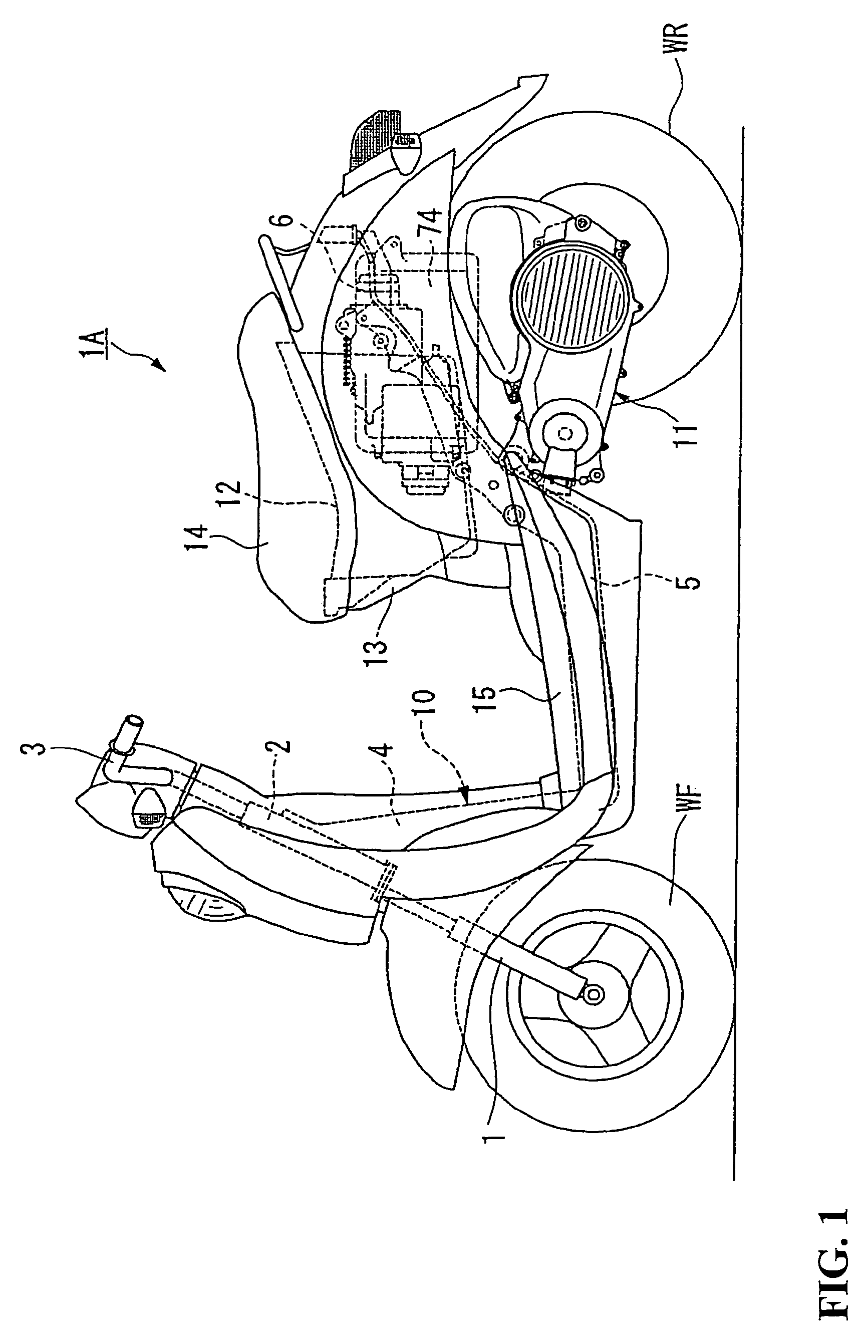
[0032]FIG. 1 illustrates a unit swing system motorcycle 1A configured as a hybrid vehicle. The motorcycle 1A includes a front fork 1 which rotatably supports a front wheel WF at the front of the vehicle body. The front wheel WF and the front fork 1 are rotatably supported by a head pipe 2, so as to be capable of steering by operating a handle 3. A down pipe 4 is mounted to the head pipe 2 so as to extend rearwardly and downwardly with an intermediate frame 5 extending substantially horizontally from the lower end of the down pipe 4.

[0033]A rear frame 6 is formed rearwardly and upwardly from the rear end of the intermediate frame 5. The front end of a power unit 11 includes an engine 20 as a prime mover of the motorcycle 1A, which will be described later, that is rotata...


PUM


Abstract

To provide an arrangement structure for bearings which overlap in the axial direction. A driven shaft and an intermediate shaft are linked to each other and are disposed to be substantially parallel with respect to each other. The driven shaft and the intermediate shaft are rotatably supported via the radial ball bearings, respectively with the respective radial ball bearings being disposed so as to overlap partly with each other in an axial view. An inner wall portion for supporting the respective radial ball bearings is provided with the respective radial ball bearings being mounted to the inner wall portion substantially in the same direction.

Description

CROSS-REFERENCE TO RELATED APPLICATIONS[0001]The present application is related to Japanese Patent Application No. 2004-011871 filed on Jan. 20, 2004 the entire contents of which are hereby incorporated by reference.BACKGROUND OF THE INVENTION[0002]1. Field of the Invention[0003]The present invention relates to an arrangement of bearings for a plurality of torque transmission elements.[0004]2. Description of Background Art[0005]FIG. 3 of Japanese Patent No. 3,039,168 discloses a structure for bearings in which a plurality of power transmission shafts are linked to each other and are arranged to be substantially parallel to each other for rotatably supporting the respective power transmission shafts via the bearings respectively.[0006]This technology has a structure in which the respective bearings are mounted to wall portions which support the bearings from both sides, so that the respective bearings are partly overlapped when viewed in an axial view.[0007]However, in the structure ...

Claims


Application Information

Patent Timeline
Patent Type & Authority Patents(United States)
IPC IPC(8): F16C19/54F16H1/06B62K11/00F16C35/06F16C35/07F16H9/18
CPCB62K11/00F16C19/54F16C35/061F16H57/021F16C41/008Y10T74/19647F16H9/18F16C35/04
Inventor TSUKADA, YOSHIAKIOZEKI, TAKASHIFURUTA, SHINJI
Owner HONDA MOTOR CO LTD
Why Eureka
Try Eureka