Locking structure for a tool box

a tool box and locking technology, applied in the field of locking structure of a tool box, can solve the problem that hand tools cannot be taken out of the tool box without permission

Active Publication Date: 2013-04-02
INFAR IND CO LTD
View PDF8 Cites 15 Cited by
  • Summary
  • Abstract
  • Description
  • Claims
  • Application Information

AI Technical Summary

Benefits of technology

[0007]The primary objective of the present invention is to provide a locking structure among the box body, the handle and the cover of a tool box, wherein the handle is a rotatable structure which can support the box body to make the box body stand in an inclined manner, so as to allow the user to have a full clear view of the hand tools inside the tool box.
[0008]Another objective of the present invention is to provide an antitheft locking structure for a tool box, when the tool box of the present invention is closed, the cover can be tightly locked to the box body and cannot be opened and removed from the box body unless the locking ends of the retainers are destroyed. Therefore, the hand tools cannot be taken out of the tool box without permission.

Problems solved by technology

Therefore, the hand tools cannot be taken out of the tool box without permission.

Method used


Image

  • Locking structure for a tool box
  • Locking structure for a tool box
  • Locking structure for a tool box

Examples


Embodiment Construction

[0019]The present invention will be clearer from the following description when viewed together with the accompanying drawings, which show, for purpose of illustrations only, the preferred embodiment in accordance with the present invention.

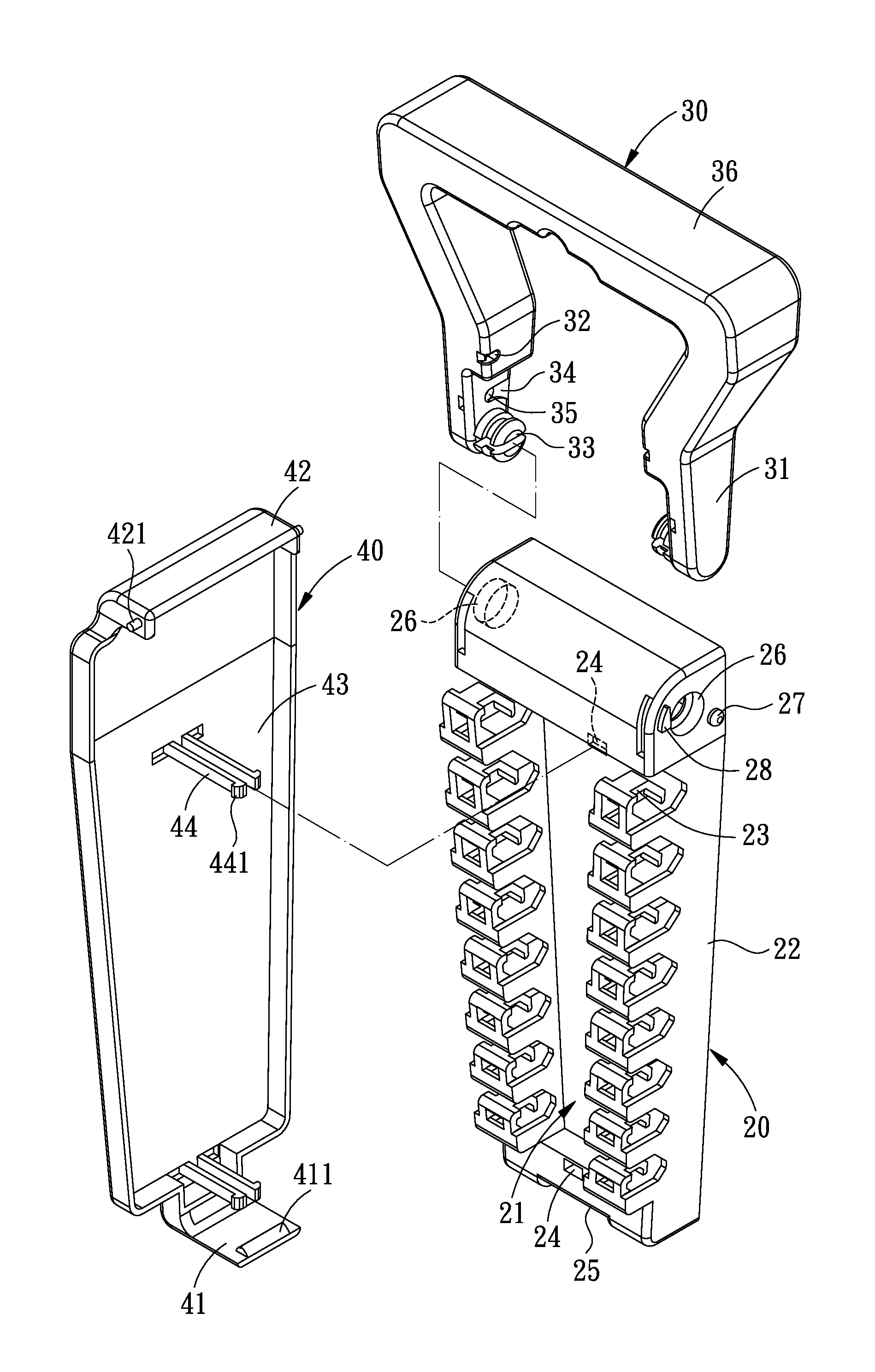
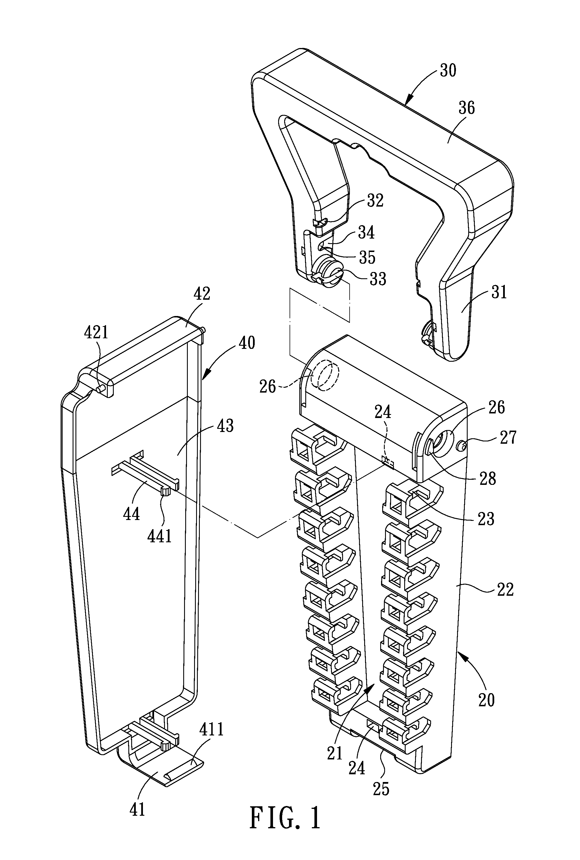
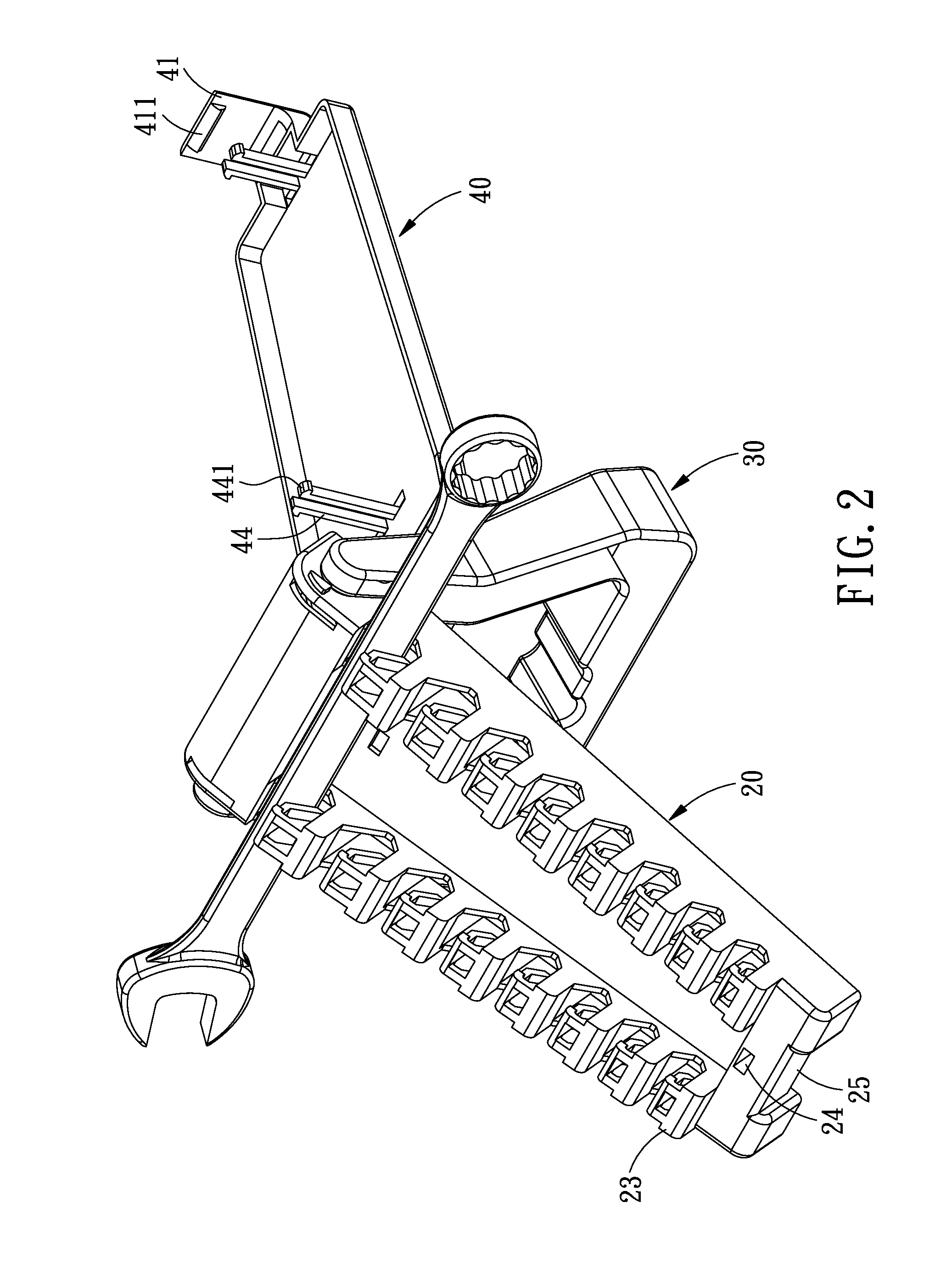
[0020]Referring to FIGS. 1 and 2, a locking structure for a tool box in accordance with the present invention comprises: a box body 20, a handle 30 and a cover 40.

[0021]The box body 20 includes a top surface 21 and two lateral surfaces 22 at two sides of the top surface 21. On the top surface 21 are provided two opposed lines of positioning hooks 23 which are arranged in an order from large to small. At each of the top and lower edges of the top surface 21 is formed a positioning hole 24. At one end of the box body 20 is formed an engaging groove 25, and at another end of the box body 20 is formed two round pivoting holes 26 which are located at the two lateral surfaces 22. Around each of the pivoting holes 26 are formed an engaging portion 27 an...


PUM


Abstract

A locking structure for the box body is provided with a box body, a handle, and a cover. The handle is a rotatable structure which can support the box body to make the box body stand in an inclined manner, so as to allow the user to have a full clear view of the hand tools inside the tool box. On top of that, the tool box offers an antitheft feature, when the tool box is closed, the cover cannot be opened and removed from the box body unless the locking ends of the retainers are destroyed. Therefore, the hand tools cannot be taken out of the tool box without permission.

Description

BACKGROUND OF THE INVENTION[0001]1. Field of the Invention[0002]The present invention relates to a locking structure for a tool box, and more particularly to the locking structure among the box body, the handle and the cover, which makes the tool box become a display hand tool box with antitheft protection.[0003]2. Description of the Prior Art[0004]Wrenches, screwdrivers and other hand tools are normally put in a tool box for display when being sold in a shop.[0005]However, most of the existing tool boxes are opened in a flat-spread-out manner, and a user is unable to see the whole inside of the too box, making it inconvenient for the user to find out the desired hand tool. On top of that, the existing tool boxes are mostly not antitheft, and the hand tools are likely to be stolen when being displayed in the tool boxes.[0006]The present invention has arisen to mitigate and / or obviate the afore-described disadvantages.SUMMARY OF THE INVENTION[0007]The primary objective of the present...

Claims


Application Information

Patent Timeline
Patent Type & Authority Patents(United States)
IPC IPC(8): B65D85/28
CPCB65D25/103B65D25/2835B65D55/024
Inventor CHEN, ANDER
Owner INFAR IND CO LTD
Why Eureka
Try Eureka