Seat cushion extension mechanism

a seat cushion and extension mechanism technology, applied in the direction of chairs, movable seats, transportation and packaging, etc., can solve the problem of long-distance displacement of the seat pan

Active Publication Date: 2013-04-02
FORD GLOBAL TECH LLC
View PDF41 Cites 60 Cited by
  • Summary
  • Abstract
  • Description
  • Claims
  • Application Information

AI Technical Summary

Benefits of technology

[0001]The present invention generally relates to a seat cushion extension mechanism, and more particularly relates to a seat cushion extension mechanism that also is pivotally rotatable to provide additional support to the legs of a user.
[0006]These and other aspects, objects, and features of the present invention will be understood and appreciated by those skilled in the art upon studying the following specification, claims, and appended drawings.

Problems solved by technology

Rotation of the drive shaft when the engagement member is in the first position causes longitudinal displacement of the seat pan.

Method used


Image

  • Seat cushion extension mechanism
  • Seat cushion extension mechanism
  • Seat cushion extension mechanism

Examples


Embodiment Construction

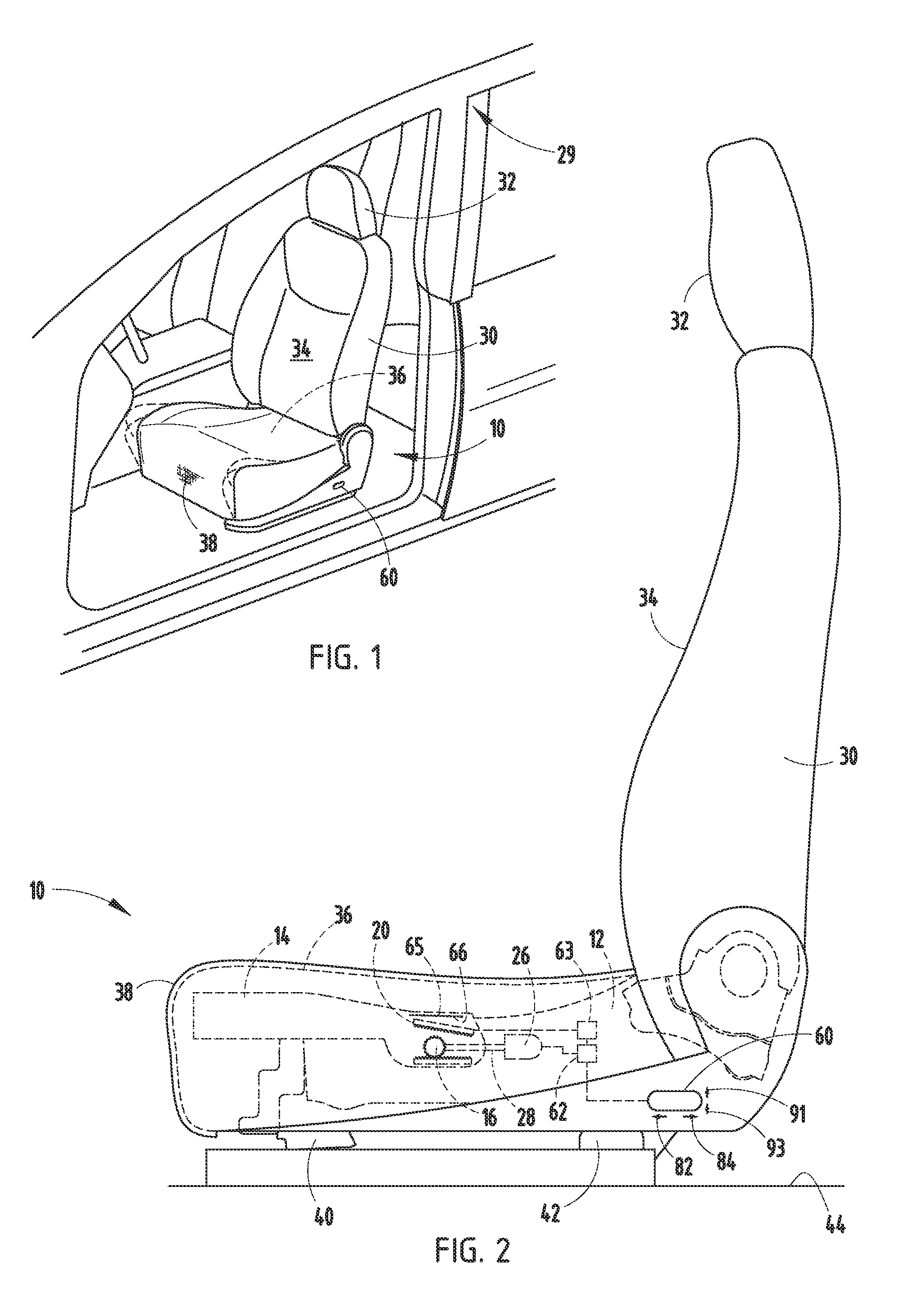
[0017]For purposes of description herein, the terms “upper,”“lower,”“right,”“left,”“rear,”“front,”“vertical,”“horizontal,” and derivatives thereof shall relate to the invention as oriented in FIG. 1. However, it is to be understood that the invention may assume various alternative orientations, except where expressly specified to the contrary. It is also to be understood that the specific devices and processes illustrated in the attached drawings, and described in the following specification are simply exemplary embodiments of the inventive concepts defined in the appended claims. Hence, specific dimensions and other physical characteristics relating to the embodiments disclosed herein are not to be considered as limiting, unless the claims expressly state otherwise.

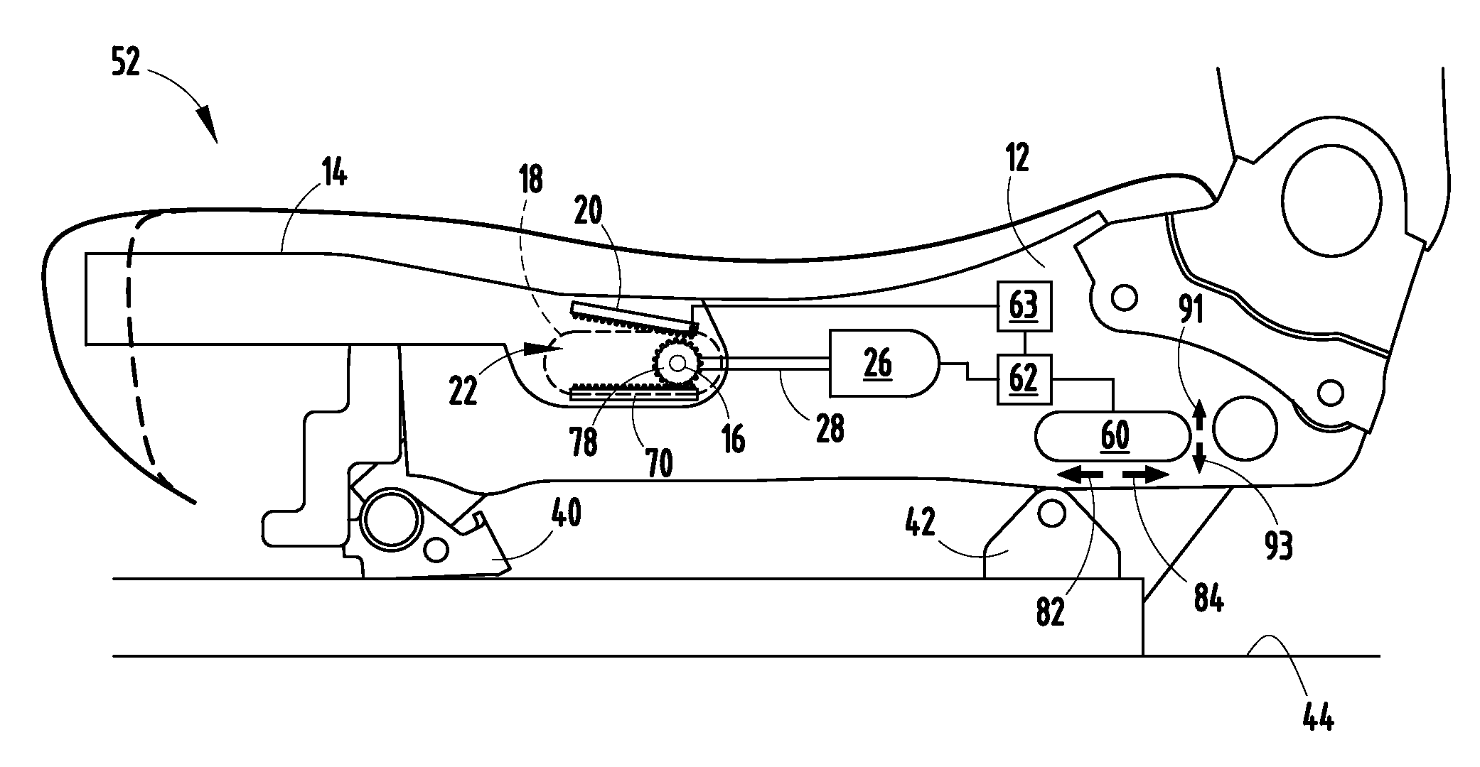
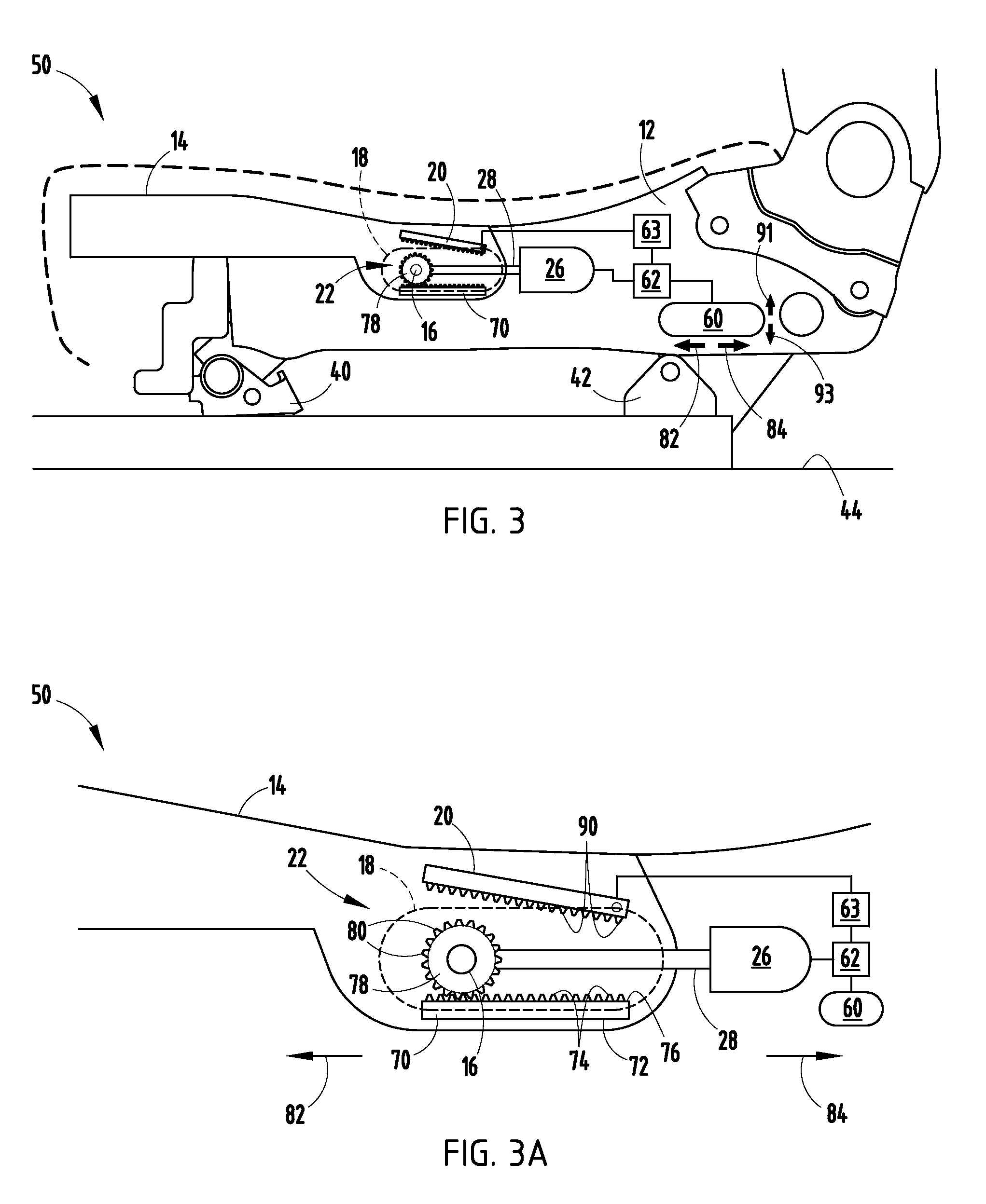
[0018]Referring to FIGS. 1 and 2, the reference numeral 10 generally designates a seat assembly having a seat base 12. A seat pan 14 is operably connected to the seat base 12. A rod 16 extends across the seat base 12 int...


PUM

PropertyMeasurementUnit
displacementaaaaaaaaaa
rotationaaaaaaaaaa
physical characteristicsaaaaaaaaaa

Abstract

A seat assembly having a seat base. A seat pan is operably connected to the seat base. A rod extends across the seat base into elongated slots in the seat pan. An engagement member is operable between a first position out of contact with the rod and a second position in contact with the rod. A motor includes a drive shaft operably connected with the rod and adapted to rotate the rod. Rotation of the drive shaft when the engagement member is in the first position causes longitudinal displacement of the seat pan. Rotation of the drive shaft when the engagement member is in the second position causes rotation of the rod and the seat pan.

Description

FIELD OF THE INVENTION[0001]The present invention generally relates to a seat cushion extension mechanism, and more particularly relates to a seat cushion extension mechanism that also is pivotally rotatable to provide additional support to the legs of a user.BACKGROUND OF THE PRESENT INVENTION[0002]Seat cushion extension mechanisms are often designed to provide support to the back of the legs of a user, but often have vertical adjustment constraints.SUMMARY OF THE PRESENT INVENTION[0003]One aspect of the present invention includes a seat assembly having a seat base. A seat pan is operably connected to the seat base. A rod extends across the seat base into elongated slots in the seat pan. An engagement member is operable between a first position out of contact with the rod and a second position in contact with the rod. A motor is provided that includes a drive shaft operably connected with the rod and adapted to rotate the rod. Rotation of the drive shaft when the engagement member ...

Claims


Application Information

Patent Timeline
Patent Type & Authority Patents(United States)
IPC IPC(8): A47C7/14A47C3/00
CPCB60N2/02B60N2/0284B60N2/1853B60N2/1875B60N2/1864Y10T29/481B60N2002/0288
Inventor HARPER, KENDRICK ALDENJESSUP, MARK DAMIENBROWN, JERRY R.
Owner FORD GLOBAL TECH LLC
Why Eureka
Try Eureka